LOL. I decided not to post my simulations because I had LTC crash until I tweaked the diodes etc. But mostly the startup is scarry with a huge over voltage surge from the inductor after the first cap is charged. I was not sure what value inductor to use because tube stuff is nothing but an amusement to me. But it's clear that it's quite picky, neither too small nor too large is OK. For low voltage capacitor coupled power supplies, using a Zener in the lower diode (and a small series cap) limits and defines the voltage nicely.
"using a Zener in the lower diode (and a small series cap) limits and defines the voltage nicely."
Can you pop in a sketch of that ?
Can you pop in a sketch of that ?
cant see why you can't use that...except that the center tap must not be used...and just one diode for negative bias, to limit current you can add a 0.1ufd cap in series with the negative bias diode.Shuffling up to breadboarding a mono amp circuit that asks for B+ of 450VDC and negative bias of -250VDC and figured I could use the power transformer I have on hand like in the sketch. Is there any reason not to do it this way? Wondering if there will be mischeif in the transformer secondary.
Thanks !
Last edited:
this one is a definite improvement...the 10ufd cap in series with the rectifier is too large for the load intended imhoWhat I find a bit scary about this style of circuit is the interdependence of the two circuits. Here see the effect of the added (or removed ) capacitor in the bridge circuit.
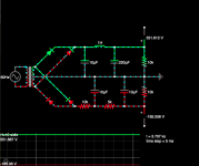
OK, I modified my simulation to show the idea. Because 250V Zeners may not exist, I used two 126V Zeners. This was an interesting simulation because inductors can easily generate ~infinite voltages that crashes LT Spice. Inductors also ring like a bell during the time after they discharge, so I added a snubber Diode + Resistor that is probably not needed in a real circuit. Hope this is useful:"using a Zener in the lower diode (and a small series cap) limits and defines the voltage nicely."
Can you pop in a sketch of that ?
Attachments

You should always add parasitic resistances to all inductors, even if their value is symbolic. It greatly helps for the convergence.Inductors also ring like a bell during the time after they discharge, so I added a snubber Diode + Resistor that is probably not needed in a real circuit.
Attachments

Ya, good idea. I should research some real inductors, but like I said, no chance I'm going to actually build any tube equipment. I had enough of tubes 40 years ago. I remember correcting terrible bias and zero engineered amps.
I'm not sure about the best efficiency of putting a Zener in this position. Too much like work? Normally we did this to create a -5V supply directly from 120VAC, so the Zener heat was not an issue. BTW, the 1uF cap could be smaller and that reduces wasted heat.
I'm not sure about the best efficiency of putting a Zener in this position. Too much like work? Normally we did this to create a -5V supply directly from 120VAC, so the Zener heat was not an issue. BTW, the 1uF cap could be smaller and that reduces wasted heat.
You should always add parasitic resistances to all inductors, even if their value is symbolic. It greatly helps for the convergence.
By the way, LTSpice adds 1 mohm of series resistance by default. I learned that when I was simulating a power electronics circuit with a 300 uohm current sensing resistor and the current level dropped by about a factor of four when I added an inductor to model the sensing resistor's parasitic inductance. I thought it was an ideal inductor, like in any other simulator, but it wasn't.
Do you mean to say the differences in measurements between the two files are entirely due to parasitic resistances in the two inductors? (I count one in the upper circuit and one in the lower.) If so, that's amazing.You should always add parasitic resistances to all inductors, even if their value is symbolic. It greatly helps for the convergence.
The capacitive supply should be tailored according to the current requirements; normally, for a bias voltage, it should be just enough to drive the bias adjustment trimmer comfortably: a few mA at most.BTW, the 1uF cap could be smaller and that reduces wasted heat.
Another possibility is to add a second capacitor, to make a capacitive divider. That way, the voltage can be brought within the right ballpark, without generating any heat
Yes, and I removed the now unnecessary snubbersDo you mean to say the differences in measurements between the two files are entirely due to parasitic resistances in the two inductors? (I count one in the upper circuit and one in the lower.) If so, that's amazing.
I looked up inductors at Hammond Mfg.
https://www.hammfg.com/electronics/transformers/choke/153-159
https://www.hammfg.com/electronics/transformers/classic/194
Note that a 5H choke is about 100 Ohms series.
But they don't say anything about self-resonance, so I did an ~AI question, which said that a 5H choke has a self-resonance around 1800Hz. LT Spice has a capacitance parameter, not self-resonance so I make it equivalent to be about 1500pF.
I dunno for sure but I suspect the shunt resistance is wishful thinking, and the choke will ring, just a bit lower frequency than without the parasitic capacitance. If anyone has such an inductor, I'd like to see some measurements.
I know that in buck regulators, it is normal to let the inductor ring after it discharges, and that probably applies to class-D amps as well. I'm not sure there is any advantage to damping it?
If your goal is fast and easy convergence, almost any non-intrusive values will do, but if you want a realistic accuracy, you need to bring more attention.
However, with lumped, scalar parameters it is impossible to completely mimic the reality: the shunt resistance depends on eddy currents (thus frequency), in the core and the wire, and the capacitance is distributed rather than lumped. In addition, some of the capacitance is not physical, but is caused by the transit delay through the winding wire.
There is no simple way to model these effects, meaning a reality check is necessary if you need good accuracy
- Home
- Amplifiers
- Power Supplies
- B+ and B- on same winding