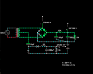
Shuffling up to breadboarding a mono amp circuit that asks for B+ of 450VDC and negative bias of -250VDC and figured I could use the power transformer I have on hand like in the sketch. Is there any reason not to do it this way? Wondering if there will be mischeif in the transformer secondary.
Thanks !
Thanks !
Attachments
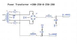

That will blow up the mains fuse (assuming there is one) as there is always a diode in D1 shorting a part of the transformer's secondary.
Assuming there is only little current flowing into the -250 V, you could disconnect the transformer centre tap from ground, and AC couple it to two diodes and a capacitor. That's probably unclear, so I will draw a schematic later.
Assuming there is only little current flowing into the -250 V, you could disconnect the transformer centre tap from ground, and AC couple it to two diodes and a capacitor. That's probably unclear, so I will draw a schematic later.
Last edited:
Well to start with, half the bridge is shorted out. The negative half of the bridge feeds nothing, a short which will burn up the transformer in a hurry. Then strangely, the "250V" circuit feeds from the high voltage taps???
A capacitor input will give you about 395V from the 280V windings and a choke input gives you about the same DC voltage as the AC voltage. I suggest you skip the lower side of the bridge and L2 and use a cap input from the 280V taps for 395V and a choke input from the 250V taps for 250V.
You also could use a bridge on the two 250V taps and a choke input for 500VDC. That puts the transformer center tap at +250 but - 250 is not easy. Assuming the -250VDC is a small current, a capacitor coupled negative supply requires some tuning and/or an inductor that will take 250VAC.
Marcel, Steveu, Yes, thanks . I see it. Lazy-bones had been 'thinking' how to whip up a quick negative bias with minimal effort and remembered Tubelab's TSE-ii supply - feeding two pairs of diodes, one solid state for the negative bias and one tube for delayed B+. Very smart and I like it. "Ooh , I'll just borrow that" and . . . . Then I got "creative". It did feel a bit like getting from Chicago to Memphis with one step when everybody else has to take considerably more, which is why I asked. : )
Instinctively I avoid using a capacitor as part of the rectifier. I know it is done but somehow I don't like it , especially with higher voltages . . . . .
It could be done with the B+ , cap couple from the winding to the bridge. Maybe good enough for a test but the cost of capacitors that would do the job long term without the least bit of worry . . . . . . nope.
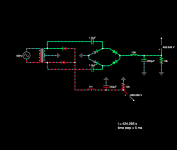
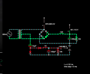
I think you already figured it out, but this is what I had in mind:

Apologies for the disproportionally large Graetz bridge.
Apologies for the disproportionally large Graetz bridge.
You may lend my smaller version (for free)!Apologies for the disproportionally large Graetz bridge.

Attachments
C3 should go to pin 1 or 3 of the transformer: 2 never goes positive enough to charge C3.I think you already figured it out, but this is what I had in mind:
View attachment 1193619
Apologies for the disproportionally large Graetz bridge.
C3 can be a lowish value film cap, and C1 can be paralleled with a string of zeners totalling 250V, to make a capacitive supply (normally, a bias voltage does not require a large current)
The absolute value of the required negative voltage is about half the positive voltage, hence the connection to a tap. Using the full secondary voltage, a small capacitor and a string of Zeners (or glow discharge tubes, although those usually require more current and have an ignition delay) is an interesting alternative, though.
Edit: I think the disadvantage of connecting pin 2 as I've drawn it is that it spends a lot of its time at a voltage with respect to ground that is close to half the peak secondary voltage, and only gets close to zero in the zero crossings of the secondary voltage. Hence, Elvee's alternatives are better.
Edit: I think the disadvantage of connecting pin 2 as I've drawn it is that it spends a lot of its time at a voltage with respect to ground that is close to half the peak secondary voltage, and only gets close to zero in the zero crossings of the secondary voltage. Hence, Elvee's alternatives are better.
Last edited:
Actually , I didn't do it that way. I used the brutish caps to bridge which is why I need higher voltage more expensive ones. The schema you posted has lower output for the same power transformer. InterestingI think you already figured it out, but this is what I had in mind:
Attachments
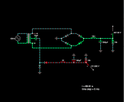
So my circuit doesn't work at all when Elvee simulates it, but it does to some extent work when you simulate it?Actually , I didn't do it that way. I used the brutish caps to bridge which is why I need higher voltage more expensive ones. The schema you posted has lower output for the same power transformer. Interesting
I have a hunch the difference is due to the filtering inductor of the +450 V output. It increases the conduction angle of the main rectifier bridge, which is also involved in getting the filtering capacitor for the negative output charged.
The example I simulated is "canonical", ie. no asymmetries in the components, etc.
A real circuit will always leak some voltage due to the parasitics, and the inductors will also certainly play a role, depending on the output currents
A real circuit will always leak some voltage due to the parasitics, and the inductors will also certainly play a role, depending on the output currents
A final point worth noting: the main supply needs to be sufficiently loaded for the auxiliary negative to work, otherwise the main supply will degenerate into a voltage doubler, and the auxiliary supply will fall to zero.
It should normally be the case, but you have to be aware of this possibility, especially during the testing/debugging phase
It should normally be the case, but you have to be aware of this possibility, especially during the testing/debugging phase
What I find a bit scary about this style of circuit is the interdependence of the two circuits. Here see the effect of the added (or removed ) capacitor in the bridge circuit.
Attachments
Ahh, I was playing around with the simulation when you posted that. I guess it's a demonstration of what you are talking about. A separate winding for the bias supply is looking more attractive.A final point worth noting: . . . . . .
What I find a bit scary about this style of circuit is the interdependence of the two circuits. Here see the effect of the added (or removed ) capacitor in the bridge circuit.
I find it more than a bit scary. My circuit is essentially unusable, and I'm glad Elvee pointed that out before anything got damaged.
- Home
- Amplifiers
- Power Supplies
- B+ and B- on same winding