gl said:Well, to be totally honest one amp has the 15 ohm Source resistors and one doesn't. I'm still messing around with that detail.
Graeme
Graeme,
I think I have one channel up and running on a test jigged output stage with 4 240s biased to 1 amp.
About 5 volts offset at start up an 7.5 mv relative offset.
The other channel has a fault with relative offset at o.6 volts...could be anything and I will investigate tomorrow.
So initally it looks promising.
I will let you know how I progress.
Ian
Both channels going now.
i'm really surprised by the low absolute and relative offset.
I should thank Erno.
No source resisters at this stage.
Ian
i'm really surprised by the low absolute and relative offset.
I should thank Erno.
No source resisters at this stage.
Ian
Hi Dave,
It's great to hear that your system is running well. I truly wish I could come over and hear it.
I chose the bipolars for cascodes because I have lots of them, they're cheap, and I don't believe that JFET's do any better in this role. I jealously hoard my JFET's saving them for more significant roles.
Hi Ian,
Congrats on getting both channels up and running and on the excellent operating specs. Now for the big questions; have you done any listening and if so how do they sound?
Graeme
Hi Graeme and William and Patrick,
Its all working I just need to refine the physical layout of my Jfet modules.
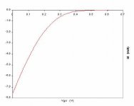
I never graphed the Transconductance curves but wonder if sme variation in bias would make any difference.
Some changes.
I diced my 4,7 uf caps...those auricaps of mine sucked in that application. The offset is about 30 mv with the X2.5 preamp
The supply rails are 23 volts.
Subjectively I like it. Definately an improvement on the 9610 input device tonally. Its has similar but not identical voicing to the X250.5 which I guess is a good thing!
Ian
Its all working I just need to refine the physical layout of my Jfet modules.
I never graphed the Transconductance curves but wonder if sme variation in bias would make any difference.
Some changes.
I diced my 4,7 uf caps...those auricaps of mine sucked in that application. The offset is about 30 mv with the X2.5 preamp
The supply rails are 23 volts.
Subjectively I like it. Definately an improvement on the 9610 input device tonally. Its has similar but not identical voicing to the X250.5 which I guess is a good thing!
Ian
http://www.diyaudio.com/forums/showthread.php?postid=1166765#post1166765
Hi Patrick ,
I have been reading Williams very interesting Aleph J thread :
http://www.diyaudio.com/forums/showthread.php?postid=1166765#post1166765
and your excellent post above regards using the 2SJ74.
The mental gymnastics of this discussion are for the moment a lot to get one’s head around.
If I ready your comments correctly there are several considerations.
The trade off of open loop gain versus open bandwidth of the first stage and the dependency of the second stage open loop bandwidth on the signal source resistance is (as you point out is essentially) determined by the drain resistor of the diff pair.
The second stage open loop bandwidth can be supported by increase feedback but only if sufficient overall open loop gain is available which is largely dependant on the open loop gain of the input stage.
Maintaining appropriate open loop bandwidth of the second stage (without much feedback) dictates a low source resistance and this in turn requires a given bias current ie 20 ma approximately for voltage requires across the drain resisters ie 4.3 volts to operate the gates of the output stage
As you point out Patrick, it is intuitive that using parallel input devices supports the required bias current and open loop gain.
Increasing the number of parallel input Jfets would further increase the open loop gain but reduce open loop bandwidth.
I have not attempted 3 pairs of devices because of the complexity but may consider it .
I am interested in your thoughts on the potential for improvement?
I have been running the amp with 2 pairs of 2SJ74 continuously for 24 hours .
Some vital signs.
Voltage across the 392R is 4.55 volts ie 11.66 ma
Relative offset 24 millivolts
Absolute offset 0.14 volts (14 volts at turn on with 68R output to ground resisters 22K McMillian resisters)
Supply rails 23 volts
Total bias = 5.37 amps
You might think 14 volts at turn on is a lot. I guess it a but it drops down quickly within a few minutes to less than 10 volts and over the course of one hour to under 200 mv. (I can see why Neslon used 30 parralell 1000R resisters in the AX200!)
I assume that the bias noted in the working circuit is a reasonable working point for an overall ids of 18.8 ma.
Please comment with recommendation if otherwise.
Ian
In the standard Aleph X circuit, you have two frequencies to worry about -- one larger determined by the apparent input capacitance of all the Power mosfets in parallel and the drain resistor of the first stage plus the equivalent gate stopper resistances of the parallel power FETs. But the apparent input resistance is also affected by gain of the second stage due to Miller effect, which depends on total power FET transconductance and output impedance.
But apparently, for reasons that I still do not fully understand, Nelson prefers to use large number of devices than necessarily, which (IMHO) does not improve transconductance much when maintaining the same total bias (but just divide that between more devices) as the FETs are still in their parabolic regime, but add capacitance proportionally to no. of devices. So maybe there is a optimal frequency to be had which is not necessarily high.
While you can lower the first stage drain resistor by paralleling more input JFETs, you also increase the input capacitances of the diff pair and hence lower the input stage bandwidth.
How these affects one another in closed loop is best investigated in Spice or another simulation software. I would encourage you to do that first before running more JFETs in parallel.
I personally no longer use the Aleph-X standard circuit but have converted it to an Xed JLH Mosfet as I published in the PLH thread, in which I use a single 2SJ109 as diff pair with 910R drain resistor, a phase splitter with cascoded 2Sk170 (because of voltage) with 500R drain and source resistor and 3x 2SK1529's in parellel as power output MOSFETs. And of course the 2SK1529 has much lower capacitance than the IRFP240 for about the same transconductance at 1.3A bias. So essentially you can still use 1 pair 2SJ74 and 900R drain with Toshiba power FETs and get the same frequency characteristics as 20mA bias and 392R drain with IR devices. My close loop bandwidth (-3dB) is 350kHz into 8 ohm resistive. Toshiba FETs sound different. It is very much a matter of taste. And there is no cheap and easy way other than to build and listen
And I would also encourage you to test (simulate) using a reactive load as proposed by Stereophile. I have published the linke somewhere on some dummy load threads over at the Solid State Forum. Please do a search.
Patrick
PS I have 2V absolute offset when cold, within 10mV between 1 hour and 2 hours, and less than 2mV relative offset. I find your DC offset high, but then I am using 10k for absolute DC feedbacl to diff pair source.
Perhaps one more comment on MOSFET choices, to at least try to be neutral.
It is noticeable recently that quite a few well-known gurus are turning to Fairchild MOSFETs. Nelson has mentioned Fairchild equivalents to IRFPs in the F5 article. Just the other day, John Curl also stated in the Blowtorch thread that Blowtorch has Fairchild (and not Toshiba as widely speculated) MOSFETs. I believe that Grey is also using Fairchild for his GR-25, if my memory still works.
On the other hand, there are still quite a large number of known designers preferring Toshiba devices. They include ASR (Emitter II uses 2SK1530 / 2SJ201), Borbely, Kaneda, etc. There are also many in the DIY forum who use Japanese devices like Toshiba, Renesas and Sanken. Again, it is a matter of taste.
I have not tried Fairchild as yet, but I prefer Toshiba to IR in the few circuits I built. And I think I am not wrong in saying that their complementary devices, especially those specifically for Audio Applications, are MUCH better complementaries than those from IR.
Of course as many here also know, I also like the LU1014 a lot, which is neither IR nor Toshiba nor Fairchild, is available still only from one source (in Germany), and has no complementary P-device. I have used LU1014 with bias from 200mA to 1.3A. Ask Steenoe. He wouldn't swap his DAO Follower for anything. But then that is another story.
😉
Patrick
Hi Patrick
You can send me your schematic please.
Habe schon eine ganze Menge Versionen AX100 durchsimuliert, komme aber zu keinem vernünftigen Ergebnis.
Bitte an folgende e-mail.
michbeh2000@yahoo.de
thanks Michael. 😉
You can send me your schematic please.
Habe schon eine ganze Menge Versionen AX100 durchsimuliert, komme aber zu keinem vernünftigen Ergebnis.
Bitte an folgende e-mail.
michbeh2000@yahoo.de
thanks Michael. 😉
The search engine on the forum is quite good. I am surprised that you could not find it :
http://www.diyaudio.com/forums/showthread.php?postid=722428#post722428
This is the lower power, MOSFET input version. The rest (high power, JFET, .....) has been published widely. I am sure you can adapt it to your own configuration without problems.
Gruss,
Patrick
http://www.diyaudio.com/forums/showthread.php?postid=722428#post722428
This is the lower power, MOSFET input version. The rest (high power, JFET, .....) has been published widely. I am sure you can adapt it to your own configuration without problems.
Gruss,
Patrick
Hi Ian,
Thank you for your last update. It sounds like you are getting the same sonic results I am. Sorry for not posting sooner. I have been away on business.
Graeme
Thank you for your last update. It sounds like you are getting the same sonic results I am. Sorry for not posting sooner. I have been away on business.
Graeme
gl said:Hi Ian,
Thank you for your last update. It sounds like you are getting the same sonic results I am. Sorry for not posting sooner. I have been away on business.
Graeme
Hi Graeme
I hope to post a pic soon.
Ian
Ian,
Speaking of pics, here's one I found recently on the burning amp site:
http://home.comcast.net/~burningamp/images/Images/Site_2/My_Albums/Pages/BAF2007_-_Vladimir.html#11
That's Nelson on the left of course, and I'm the gent in the blue shirt standing behind Variac's F4. And I believe that that's Jan Didden standing behind me in front of the window.
Yes, I was feeling as tired as I look. Had to get up at an ungodly hour to get there at a reasonable time.
Cheers,
Graeme
Hi Graeme,
I would like to run some ideas past you.
Have your tried alternative gain and feedback.
I am building an Aleph J with a friend in the USA and I find in the manual and schematic some interesting tips .
15 db less feedback (and noise)
19.6 db gain (x 10)
comparable distortion to the original Aleph 3
Reduced current gain for better performance in 8 /16 ohms.
I am not suggesting a re write of the entire X J Aleph because they are different but it might be fun to swap out the input toi ground resisters for higher values and see what happens.
How did you arrive at the gain of 26 db earlier?
I might also go the other way and try 10K to ground resisters and or 100 K feedback and a 3rd set of parralell Jfets if time permits. In this instance the sources resisters would be more applicable to reduce capacitance and distortion per Borbely article
Ian
Hi Ian,
You ask a number of questions in your post and some of them are beyond my experience and ability. But I'll give it shot!
1) I have not tried alternative gain and feedback values other than the experiments I've made with the MacMillan resistors.
2) The Aleph J numbers you give were selected by Nelson and he clearly had reasons for selecting them. It would be best for him to comment rather than have me guess.
3) I tried several values of input to ground resistors: 10K, 22K, 47K, and 100K. Only the 22K value had acceptable relative offset numbers. I don't know why. The Aleph J uses 220K here but it's a very different topology.
4) I chose 26dB because 1) that's what Nelson used in the original XA series amplifiers, and 2) it's a common value in the industry and worked well in my system with my pre-amp. Note that Nelson now uses 30dB of gain in some current PL product because that's a new common value in HT applications.
I don't think that there's a better or worse regarding high-gain vs. low-gain amps. You need a certain amount of gain between your playback device and your speakers. You use a smaller number of gain stages with high-gain or a larger number of stages each with lower gain. Or you use some combination of these two. It's all a trade-off. That's what makes life interesting.
5) Using another pair or two of JFET's would probably improve things IMO. You would get more transconductance, more current to drive the second stage (assuming you stay with 4-5ma per JFET), and less noise. IMO the increase in input capacitance is not a big deal particularly if you use cascodes. The only real negative I see is the increased cost and complexity, but you appear to have accepted that already. So go for it. I have no opinion regarding your proposed 10K and 100K resistor values.
I look forward to hearing about your results.
Cheers,
Graeme
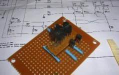
Here is one of my XJ Aleph front end Jfet diy pcbs almost done.
I attached the jfets to thin slice of vero board.
The soldered tinned wire flying leads to the underside which mate with the geomtry of the lower vero board that holds the cascode ZTX 550, links for the gates & source of the Jfets and when I am done the input divider and drain resisters (392R).
About 100 solder joints later........
Attachments
Graeme,
I dont think there is anything wrong with the way you the amp.
I wrote Neslon (in his jammies) and he suggests those are pretty typical values,and there's no reason one can't lower the gain via the large resistor as it gives slightly better bandwidth.
The 22K to ground resisters throw away 3 db feeback, but apparently its worth it.
I hope Nelson does not mind me sharing these few snippets of gold.
Ian
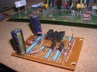
Here is the input module.
I moved the input divider onto the module and the drain resisters 392R and will run the Gate wires straight from the module. In an attempto to ensure the drains see the same potential as the outputs I have included some local bypassing.
The 22K input to ground resisters are mounted on gold pins for ease of access. All the connections are via pins so I can wip out the board to modify/update.
The tihrd set of Jets can be enaged with addition of some links and extra ZTX550s and Dale 15R resisters and trim pots to adjust the bias the drain resisters.. I will look at this later on.
Ian
Attachments
- Status
- Not open for further replies.
- Home
- Amplifiers
- Pass Labs
- AX100 100W Aleph-X Monoblocks