2 Zener diodes are near audio section? If you meant those then they have 3.5V across them and they are IN4744A.
1N, not IN. They are 15v Zeners and if you have 20+v on the resistor, you should have ~15v on the diodes. Desolder them to see if they're leaking. Do NOT power up the amp with the Zeners out of the circuit.
I read from internet, that zener diodes should be checked with variable power supply or analog multimeter. I dont have either. I just checked them with my digital multimeter using diode check function. Probes one way: open circuit, probes the other way: 1.540.
I'd expect open one way and 0.7v with the probes reversed. 1.54 is a bit much. Does your meter read ~0.6v when testing other diodes?
You don't need a variable supply to test Zeners.
You don't need a variable supply to test Zeners.
I will test them again and try to find some working diodes to compare results.
What if they are defective? That is not the cause of the problems this amp has, its rather the result?
What if they are defective? That is not the cause of the problems this amp has, its rather the result?
ok, just a slight perspective here..... i had an amp recently, and being 15 years old, i wanted to go through and re-solder any dry joints i found. instead, i found a large mess of over-soldering and excessive flux. well, i began de-soldering all the excess, and re-soldered fresh, then defluxed the whole thing. then, i powered it up for the first time, and got dc output from one channel. went through all kind of process of troubleshooting form removing the outputs, isolating circuits, etc.... at one point i even had it playing poor quality on that one channel, and great on the other. well long story short, there was one jumper that crossed an open trace, and the fold was so close that it just touched, and had an output feeding itself. i do remember the output drive having a similar reading of 7/21/7, or something like that, which i thought was defective untill i pulled it. by your account of how physical manipulation of the board effects what it does at times, i would go over the board with a fine-tooth comb, even if it just eliminates coincidental symptoms and helps find the real problem. worked for me. /my .02
Thanks for input. I will check the board to see if there are connections where they should not be. Right now its just frustrating, each time I feel that I am getting somewhere, symptoms just disappear or new symptoms will develop.
Sometimes it helps to document the voltages at several points when an amp has this sort of problem. When something changes, you can go back and check them all to see what has changed. You don't need to post the voltages but I'd suggest that you measure and make a note of the following points:
Voltage inside the amp on the circuit board for the B+ and remote. Place the black probe on the ground on the circuit board inside the amp (beyond the ground terminal).
The DC voltage on all 3 terminals of the power supply FETs (at least one from each of the 4 banks of FETs)
All of the pins of the power supply IC
The rail voltage on each output transistor
The regulated voltage on the op-amp power supply terminals
If there is some bad connection or something like that on the board it will be a nightmare to find. At least I did not find anything like that, but I found something interesting.
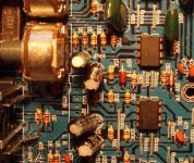
On picture 3 of the first post of this topic there are power supply FETs and near them, there are resistors and very small capacitor. One of the capacitors is missing.
What is that capacitor for and what happens if it is missing?
I will take those Zener diodes with me to work tomorrow, electrician has very good multimeter, I will let him to check them.
Those look like improperly connected snubbers.
Whatever they are, the missing cap isn't likely to cause intermittent problems.
Whatever they are, the missing cap isn't likely to cause intermittent problems.
Tested the zeners with electricians multimeter.
Open one way, 0.675V the other way, that means they are good.
I am out of ideas.
Yesterday I reinstalled the zeners, found a cap with similar value to the one that was missing. Tried the amp, everything is the same, instead of 15V I have 3.5 and resistors are getting hot. Thought that maybe TL072 which I inserted is the cause? Removed it and still 3.5V.
If power supply chip has output and I have 21V rail voltage - means that transformers are OK?
I noticed earlier one more thing which I did not think was important at the time.
Near inputs there is opamp? with 9 legs drawn to the board but the opamp itself is not there.
It looks like it has never been there, maybe its for some other model which uses the same board? By the looks of it, it has something to do with RCA outputs and can not cause the problems this amp is experiencing?
Photo attached.
Attachments
There could be problems with the transformers that are intermittent. Since the amp isn't drawing excessive current and there isn't 12v on the secondary ground, they are OK right now.
Do you have a large 2 ohm current limiting resistor, an automotive headlamp or any other type of current limiter that you can use in series with the B+ line?
Do you have a large 2 ohm current limiting resistor, an automotive headlamp or any other type of current limiter that you can use in series with the B+ line?
Wait, secondary ground? What/where is secondary ground? I measure voltages between point and ground terminal all the time, I am supposed to measure ground from somewhere else?
You can use the non-bridging speaker terminals for the reference (black probe). The non-bridging terminals, the RCA shields and the secondary center tap are all likely directly connected in this amp.
With the black probe on pin 4 and the red probe on pin 8 of any 8 pin op-amp in the preamp section of the amp, what is the resistance (no power applied, leave the probes in place until the readings stabilize).
Yesterday I cleaned the board thoroughly and left it to dry overnight in a warm place. Today I put the amp back together and noticed it did not draw current and had -14V and +15V on opamps legs, 0.5, 21, 0V on output transistors legs, same on audio section small transistors. Power supply transistors legs 3,5V, 11V, 0V.
Then connected speaker, for a few seconds it made some noise, cone did not get pushed out anymore, amp did not draw current.
Switched amp off, connected RCA and iPod to see if it produces audio, switched amp on and then speaker made only noises all the time, amp started to draw current, and voltage on op amps legs got down to 2V.
Resistance between opamps power supply legs, (black on negative supply leg, red on positive, amp switched off, before switching off voltage on op amps supply legs 2V) multimeter set to 20kOhm setting: 0,08, vice versa 0,01.
- Status
- Not open for further replies.
- Home
- General Interest
- Car Audio
- Auna ALP404CH two channels drawing exessive current when speaker connected