50Hz isn't a problem.
Did you look at the signals in differential mode?
Use DC coupling in differential mode. Align the trace to the reference line.
Did you look at the signals in differential mode?
Use DC coupling in differential mode. Align the trace to the reference line.
For the differential image, one probe would be on the source pad of the output FET and the other on the drive signal.
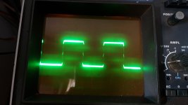
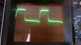
Photo 1 is the high side gate drive
Photo 2 is the low side gate drive
Trace is aligned in the reference line before measuring.
If I understand this principe correctly, this differential measurement is done to check if the spikes on top of the PWM is real or a inductive/magnetic measurement interference. Is this right? Could you confirm this please? 🙂
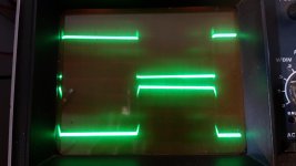
Attachments
Using differential mode gives the scope a better reference and allows you to see DC offset.
Neither signal appears to be going back to ground.
Confirm that the scope is reading as expected by checking the signal with the probes on the gate and source of the PS FETs.
Neither signal appears to be going back to ground.
Confirm that the scope is reading as expected by checking the signal with the probes on the gate and source of the PS FETs.
Double-check your scope for these settings.
Input set to add
Both channels set to DC coupling.
Both channels set to 'cal'.
Both vertical amps set to the same voltage
Ch2 input set to invert
Bandwidth limited (works best for most measurements in car amps)
Trace aligned to the reference line on the scope's display
Input set to add
Both channels set to DC coupling.
Both channels set to 'cal'.
Both vertical amps set to the same voltage
Ch2 input set to invert
Bandwidth limited (works best for most measurements in car amps)
Trace aligned to the reference line on the scope's display
Looking more carefully at the graticule (difficult to see), it now appears that one signal is going below ground.
Do you have channel 2 (inverting channel) on the source leg of the FETs and the ch1 probe on the drive signals?
Do you have channel 2 (inverting channel) on the source leg of the FETs and the ch1 probe on the drive signals?
To both statements, correct.
It seems to drop juuuust below ground on the PS gate drive.
The fets in every bank seems to switch happily. They stay absolutely stone cold.
It seems to drop juuuust below ground on the PS gate drive.
The fets in every bank seems to switch happily. They stay absolutely stone cold.
Last edited:
The PS drive is OK. I was looking back at the other two waveforms you posted in differential mode.
Ah, excuse me.
Also in this case, to both statements, yes.
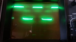
It's the low side gate drive
Differentail mode measurement, probe 1 on the driver board output pin, probe 2 on the source pad results in the same.
Also in this case, to both statements, yes.
It's the low side gate drive
Differentail mode measurement, probe 1 on the driver board output pin, probe 2 on the source pad results in the same.
Last edited:
With the ch2 probe on the same point (low-side source pad), probe the -vccs on the driver board, what sort of signal do you see. Set both channels to 1v.
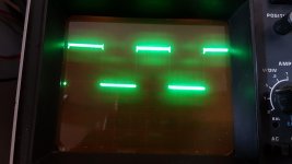
In differential mode and both channels to 1v, a straight line -4v below middle reference line
Last edited:
Are the two shunt resistors within tolerance?
You should read essentially 0 ohms between the -vccs and the source pad of the low-side FETs.
You should read essentially 0 ohms between the -vccs and the source pad of the low-side FETs.
- Home
- General Interest
- Car Audio
- Audison SR1Dk output driver card, no High-side output