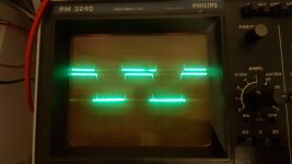
Yes, the drive wave looks even slightly better with capacitor connected across.
The little spikes on the top are gone with the capacitor. Looks pretty clean.
The little spikes on the top are gone with the capacitor. Looks pretty clean.
What's the oscillation frequency that you're seeing in the recent tests with no output FETs installed?
A very low frequency. About 50-100Hz I think. It's the same oscilloscope settings when I check 50-100Hz sine waves.
It only starts oscillating when there is an audio signal present on the RCA.
It only starts oscillating when there is an audio signal present on the RCA.
Will it oscillate at operating frequency (near 100kHz?) with at least one FET in each bank and the inductor out of the circuit (at least one leg desoldered)?
Is this with the inductor out of the circuit?
If so, look at the high and low drive signals (no FETs) at the same time to see if there is any overlap of the signals.
If so, look at the high and low drive signals (no FETs) at the same time to see if there is any overlap of the signals.


Set vertical amplifiers to 'cal'.
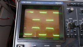
Is the difference in the waveform shapes real or is it one channel of the scope that reads it differently?
Is the difference in the waveform shapes real or is it one channel of the scope that reads it differently?
Vertical amplifiers are calibrated. They had an offset, but are calibrated on the photo.
The difference in waveform shapes is real.
The difference in waveform shapes is real.
The 3rd photo shows them off of cal.
Is the voltage across terminals 5 and 8 of the two optocouplers very nearly the same?
The amplitude of the signals is different. With the channnels to to cal, is their amplitude the same? Check both with one channel.
Is the input to both optocouplers the same?
Are the outputs of both optocouplers directly connected to the header pins of the driver board?
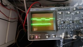
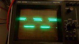
I made 2 new photos from the output fet drive waves.
This one seems to be more solid then the previous.
By eye the waveform looks excactly the same, just a liiitle amplitude difference. This frame flashes with 50Hz.
With photo it looks like this:
This one seems to be more solid then the previous.
By eye the waveform looks excactly the same, just a liiitle amplitude difference. This frame flashes with 50Hz.
With photo it looks like this:
Attachments
The voltage on Pin5 and Pin8 of the optocouplers is different.
One is 15.38v and the other (voltage is delivered by a battery) is 11.38v.
Because there are no fets in the circuit.
The inputs of the optocouplers is 100% identical.
The output of the optocoupler is directly connected to the header.
One is 15.38v and the other (voltage is delivered by a battery) is 11.38v.
Because there are no fets in the circuit.
The inputs of the optocouplers is 100% identical.
The output of the optocoupler is directly connected to the header.
From what I see, one signal has very square corners with a bit of overshoot/spiking. The other has rounded corners. What am I missing?
I plugged in a battery which has excactly 15.38v too.
Both optocouplers have the same voltage.
This does not change anything.
Both optocouplers have the same voltage.
This does not change anything.
One thing I forgot to mention, which might be important.
This amplifier needs a music signal in order to create a output fet drive wave.
All measurement tests are done with a 50Hz RCA tone.
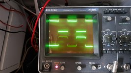
One thing comes to my mind, on my last 2 photo's you see 2 completely different period times of the square waves. On photo 1 the upper square wave is overlapping, on the second photo the square wave from the down side is overlapping.
Could this 50Hz tone be the reason of overlapping?
Changing the RCA frequency changes the output drive wave as well.
This amplifier needs a music signal in order to create a output fet drive wave.
All measurement tests are done with a 50Hz RCA tone.
One thing comes to my mind, on my last 2 photo's you see 2 completely different period times of the square waves. On photo 1 the upper square wave is overlapping, on the second photo the square wave from the down side is overlapping.
Could this 50Hz tone be the reason of overlapping?
Changing the RCA frequency changes the output drive wave as well.
- Home
- General Interest
- Car Audio
- Audison SR1Dk output driver card, no High-side output