I'm curious about a few things so I thought I might start a discussion.
Any comments on this design? From the scope traces it looks like the reduction in distortion is an order of magnitude better than the Analog Devices accelerometer-based servo sub. I suspect AD's implementation suffered so badly from phase shift that most of its value is eliminated; I don't think a 10-20% reduction in THD is really that significant in a sub.
1. There are seperate adjustments for current sense gain and sense coil gain. The author states he adjusts these until he finds a combination where they are "similar"...similar to what? What is the proper adjustment procedure?
Since R17 is not affecting the feedback to signal ratio I would guess that that sense coil adjust determines the amount of feedback and the current sense adjust is used to null the error. But how do we determine when the error is lowest? The author doesnt seem to offer any hints.
I wonder if adding another adjustable buffer stage after the differentiator might not be a bad idea. That way you wouldn't have to null the error again if you change the feedback ratio.
2. This design appears to have been tested at low power, although that is not stated anywhere. When applied to 12"-15" 250-1000W design, will the higher currents cause the design assumptions to fail?
Any other comments? The magnitude of distortion reduction means I will definitely be trying this at some point, but I wonder if it will be as effective with my Shiva as with the 8" peerless.
Hi,tiroth said:There are seperate adjustments for current sense gain and sense coil gain. The author states he adjusts these until he finds a combination where they are "similar"...similar to what? What is the proper adjustment procedure?]
IMHO:
In the equation for sensor voice-coil voltage Vs(t)=c(dx/dt) + M(di1/dt), the first part may be made equal to zero if we block the coil from moving. The result is that the Vs(t) is equal to M(di1/dt). When we apply signal to the speaker (low level - 1W or so), we can set null at the output of the opamp D, with the relative changing of R1 and R9.
Since R17 is not affecting the feedback to signal ratio I would guess that that sense coil adjust determines the amount of feedback and the current sense adjust is used to null the error. But how do we determine when the error is lowest? The author doesnt seem to offer any hints.]
By measuring distortion with microphone and by setting the absolute levels of R1 and R9 to minimum distortion.
I wonder if adding another adjustable buffer stage after the differentiator might not be a bad idea. That way you wouldn't have to null the error again if you change the feedback ratio.]
Or placing a trimer resistor (10k) instead of R15 to do the job.
This design appears to have been tested at low power, although that is not stated anywhere. When applied to 12"-15" 250-1000W design, will the higher currents cause the design assumptions to fail?]
IMHO, applying servo makes sense only in low-power (HI-FI) designs.
Regards
Although I work in a coherent transient world instead of a steady state world (sine waves) or chaotic world (noise) I am responding to the query for “any comments.”
For me it was a thought-provoking article. In that way the article had value even if I don’t build one of the circuits.
I like the idea of trying to cancel out voice coil cross talk. I am not certain the assumption of a relationship between current flow in the drive coil and cross talk to the sensing coil is valid. If it is, then at system resonance, where feedback might be most useful, almost no cancellation will occur. In a sealed system, the impedance goes high at system resonance, little current will flow and almost no difference voltage will appear across R7. If that is the case, considering the low pass filter knee point of about 100 Hz, then I am uncertain at what operating frequencies the cross talk cancellation circuit will be valuable. From my own experimentation, cross talk at system resonance is not a concern.
General comments:
First, the technique will work with other drivers just as well as it works with the Peerless driver.
Two, if you go higher in power watch for clipping or overloading of the op amps. Voltage off the sensing voice coil will come close to the voltage applied to the drive coil. I also am uncertain how much headroom is provided with the so-called differentiator circuit. These are not fatal flaws, just things to watch.
Three, this is a complex circuit with lots of op amps. Watch for oscillations in any of these op amps. The breadboard photograph shows LF347N IC s with no high frequency power supply by-pass caps on the board. This is a circuit for the person who loves to “tweak,” has access to a high bandwidth oscilloscope, and some way to protect both amp and driver during initial set up.
Four, I wish the author had better instrumentation available to test his design. Single frequency sine wave testing can be misleading. A matter of author’s choice was involved in choosing photographed sine wave frequencies for the article. Even the student paper on AD’s Web site showed frequency dependent differences in distortion reduction.
Five, I wish we were told how much feedback was actually achieved using the design. Looking at the RTA graphs, you cannot tell. If closed loop feedback is high, then the author has adjusted for the decreased sensitivity.
Six, I wanted to see a “phase” comparison between the drive sine wave and the differentiator output in addition to the comparison between the sensing coil output and the differentiator output. How close is the processed sensing signal to temporally matching the drive voltage and how much mismatch is there between the drive signal and the sensing coil signal? With a complex, broadband signal, a mismatch can produce ripple in the acoustic output that 1/3 octave analysis is unlikely to detect.
In sum, the circuit will work to provide MFB for a woofer, but while the cross talk canceling circuit is a nice idea it may not provide any real benefits. I am also suspect of how the combination differentiator/integrator circuit will work in the transient world. I can’t promise I will ever build and test this circuit, but if I do I will post results to this thread.
Mark
Hi tiroth,
is it possible to find that article somewhere in the internet?
It's quite hard to get a copy of audioXpress here in Germany.
Zelter
is it possible to find that article somewhere in the internet?
It's quite hard to get a copy of audioXpress here in Germany.
Zelter
Not to my knowledge. I'm afraid that I do not have a scanner or I would be happy to send it to you. Perhaps someone else can oblige?
I recieved a copy, from Rarkov (excuse my spelling, it's from memeory) I do believe, it was mentioned in another thread. I had many doubts about the differentiator circuit, and would like a better way of doing it, maybe an OPA541 could play a role here (or simmilar OPA54X chips, not sure which is suited for this) for +/- 15V is not enough for my use, a normal opamp will clip in this situation especially if you're eq'ing the bottom end.
The crosstalk did seem to be maybe wirthwhile if it indeed does have a large effect, but I wished the author had taken measurements with both parts of the circuit appart (crosstalk elimination and differentiation).
I'd like to try the differentiation, for with normally a 90 degree phase difference between the input (into the first voice coil) and output (out of the second voice coil)) signals is rather large and even if not perfect, I think that differentiation would be able to improve on that. I think I'll go the OPA54X route and see what I can achieve, unless anyone has an idea for a better or easier way (not enough time for all these projects)...
Hi everibody,
could someone post a copy of the article or send it to me private?
I'm just working with a dual voice coil driver to create a regulated subwoofer.
Zelter
could someone post a copy of the article or send it to me private?
I'm just working with a dual voice coil driver to create a regulated subwoofer.
Zelter
FYI;
The same driver that Dan Ferguson used in the article
(Peerless 831858) is on the Madisound sale page for
27.50 USD
Hey moamps,
How would you block the driver to stop the coil from moving?
I'd like to give this a try.
herm
The same driver that Dan Ferguson used in the article
(Peerless 831858) is on the Madisound sale page for
27.50 USD
Hey moamps,
How would you block the driver to stop the coil from moving?
I'd like to give this a try.
herm
herm said:How would you block the driver to stop the coil from moving?
Hi,
Practicaly speaking, this isn't easy task.
I was trying this with one cheap Monacor TC speaker by pushing cone maximum inside the speaker, and then applying small power (half watt) on it. Generated voltage (unloaded) in receiver coil was ca 10 times smaller then on generator coil in low frequency range. This isn't the best method especially if coil isn't long type.(M is changing with coil position..... anyway this is "part of linearity problem").
Regards
MOAMPS wrote:
Risking oversimplification, isn't this an approximation of crosstalk?
If so, then we can expect crosstalk to be at least 20 db down (10 to 1 voltage ratio) at low frequencies.
How much MFB do we need? If it is less than or equal to 20 db, then perhaps we could do away with the crosstalk circuits.
Just wondering,
Mark
I was trying this with one cheap Monacor TC speaker by pushing cone maximum inside the speaker, and then applying small power (half watt) on it. Generated voltage (unloaded) in receiver coil was ca 10 times smaller then on generator coil in low frequency range.
Risking oversimplification, isn't this an approximation of crosstalk?
If so, then we can expect crosstalk to be at least 20 db down (10 to 1 voltage ratio) at low frequencies.
How much MFB do we need? If it is less than or equal to 20 db, then perhaps we could do away with the crosstalk circuits.
Just wondering,
Mark
Yes, is. Do you have better idea?😉MarkMcK said:Risking oversimplification, isn't this an approximation of crosstalk?
[/B]
In this case, yes. I don't know values of M for another drivers.If so, then we can expect crosstalk to be at least 20 db down (10 to 1 voltage ratio) at low frequencies.
[/B]
I don't know M for this particular driver. If crosstalk is small, I agree with you, this circuit isn't necessary. Also, in EW Feb. 97 was published article "Roaring subwoofer" with identical MFB concept without crosstalk circuits.How much MFB do we need? If it is less than or equal to 20 db, then perhaps we could do away with the crosstalk circuits.
[/B]
Regards
Just a quick update on the design analysis and crosstalk considerations. Since I have designs and deadlines of my own to meet, I am going to have to take a break from this project for a while.
Several questions are still pending. Do we need to be worried about crosstalk? How much crosstalk exists in any given driver? How do we determine if we need to cancel crosstalk?
The test procedure given in an earlier post may fall short of an accurate technique of measurement. The total field strength over the area of the voice coil is important to the amount of mutual inductance of a dual voice coil sitting in that magnetic field.
If the coil completely leaves the gap before bottoming, the flux strength, as averaged over the total area of the coil will be greater than when the coil is centered in the gap, and the crosstalk will be greater. Every driver I have ever seen has a magnet structure deep enough to allow the voice coil to completely leave the gap before bottoming and yet shows increasing inductance with maximum at bottom. Thus the technique of pushing in the cone to its limit and holding it there to null the circuit will overestimate the amount of crosstalk. Unfortunately, the only accurate way to test mutual inductance when the voice coil is within the normal excursion limits and is more or less “centered” in the magnetic field and null the circuit within usage boundaries requires destructive testing.
In an attempt to see if there are any possible “rules” to estimate crosstalk without destructive testing, I willingly destroyed a couple of woofers.
Voice coil inductance and crosstalk were measured in three positions; voice coil removed from magnet structure, voice centered and “locked” in gap, and voice coiled bottomed and “locked.”
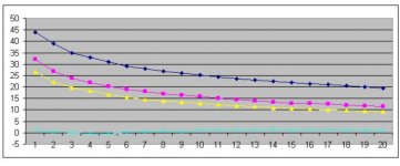
The inductance of one coil was .7 mH “free field”, 1.15 mH when centered in the magnetic gap, and 1.34 mH when bottomed. The crosstalk between 10 Hz and 200 Hz is shown in the graph. Blue is “free field,” purple is center gap, and yellow is bottomed.
While the numbers of samples is still too small for gross generalization, but there is a suggestion of correspondence between measured inductance and crosstalk. With this limited sample, it is close between the values of 1.15 mH and 1.34 mH, and with a 14 % error between .7 mH and 1.34 mH.
Pending testing of one (or more) of the very high inductance subwoofer drivers, I hypothesize that even these drivers will have 10 to 15 db of separation over the frequency range of most interest for MFB designs.
Looking for an easier way to measure inductance, I tested an inexpensive digital LCR meter to check suspended and locked voice coil inductance. The inductance measured very close (no more than 2% difference) for the two test conditions. As a generalization, it appears that the current used by the tester is insufficient to overcome suspension resistance and create any significant back emf (“c” in the formula given in an earlier post). Even if the manufacturer does not provide this specification, it seems easy to measure using a digital LCR meter.
Lastly, how well does the crosstalk canceling circuit work considering the measured mutual inductance crosstalk? For right now, I cannot make a judgment. Something is wrong with my device under test. The blue line shows the variance in frequency response across the .1-ohm resistor with the circuit constructed as drawn in the article. While the crosstalk varies markedly over the 10 Hz to 200 Hz range of the test, the decibel change caused by amplification of current flow determined voltage across the .1 ohm resistor is extremely small. The maximal deviation is only 1.5 db. System resonance for the box/driver combination is 42 Hz. This shows up in the response, it is just compressed in magnitude. I do not know what has gone wrong.
By some simple tests, the circuit appears to be working. There is no offset. When the voltage supply to the op amp is disconnected, an AC voltmeter connected to the output of difference amplifier A reads the voltage applied to the voice coil. When the power is turned on, the AC voltage on the output of difference amplifier A drops. This would be expected since Vout is determined by the voltage difference between Vin1 and Vin2
Several questions are still pending. Do we need to be worried about crosstalk? How much crosstalk exists in any given driver? How do we determine if we need to cancel crosstalk?
The test procedure given in an earlier post may fall short of an accurate technique of measurement. The total field strength over the area of the voice coil is important to the amount of mutual inductance of a dual voice coil sitting in that magnetic field.
If the coil completely leaves the gap before bottoming, the flux strength, as averaged over the total area of the coil will be greater than when the coil is centered in the gap, and the crosstalk will be greater. Every driver I have ever seen has a magnet structure deep enough to allow the voice coil to completely leave the gap before bottoming and yet shows increasing inductance with maximum at bottom. Thus the technique of pushing in the cone to its limit and holding it there to null the circuit will overestimate the amount of crosstalk. Unfortunately, the only accurate way to test mutual inductance when the voice coil is within the normal excursion limits and is more or less “centered” in the magnetic field and null the circuit within usage boundaries requires destructive testing.
In an attempt to see if there are any possible “rules” to estimate crosstalk without destructive testing, I willingly destroyed a couple of woofers.
Voice coil inductance and crosstalk were measured in three positions; voice coil removed from magnet structure, voice centered and “locked” in gap, and voice coiled bottomed and “locked.”
The inductance of one coil was .7 mH “free field”, 1.15 mH when centered in the magnetic gap, and 1.34 mH when bottomed. The crosstalk between 10 Hz and 200 Hz is shown in the graph. Blue is “free field,” purple is center gap, and yellow is bottomed.
While the numbers of samples is still too small for gross generalization, but there is a suggestion of correspondence between measured inductance and crosstalk. With this limited sample, it is close between the values of 1.15 mH and 1.34 mH, and with a 14 % error between .7 mH and 1.34 mH.
Pending testing of one (or more) of the very high inductance subwoofer drivers, I hypothesize that even these drivers will have 10 to 15 db of separation over the frequency range of most interest for MFB designs.
Looking for an easier way to measure inductance, I tested an inexpensive digital LCR meter to check suspended and locked voice coil inductance. The inductance measured very close (no more than 2% difference) for the two test conditions. As a generalization, it appears that the current used by the tester is insufficient to overcome suspension resistance and create any significant back emf (“c” in the formula given in an earlier post). Even if the manufacturer does not provide this specification, it seems easy to measure using a digital LCR meter.
Lastly, how well does the crosstalk canceling circuit work considering the measured mutual inductance crosstalk? For right now, I cannot make a judgment. Something is wrong with my device under test. The blue line shows the variance in frequency response across the .1-ohm resistor with the circuit constructed as drawn in the article. While the crosstalk varies markedly over the 10 Hz to 200 Hz range of the test, the decibel change caused by amplification of current flow determined voltage across the .1 ohm resistor is extremely small. The maximal deviation is only 1.5 db. System resonance for the box/driver combination is 42 Hz. This shows up in the response, it is just compressed in magnitude. I do not know what has gone wrong.
By some simple tests, the circuit appears to be working. There is no offset. When the voltage supply to the op amp is disconnected, an AC voltmeter connected to the output of difference amplifier A reads the voltage applied to the voice coil. When the power is turned on, the AC voltage on the output of difference amplifier A drops. This would be expected since Vout is determined by the voltage difference between Vin1 and Vin2
Attachments
I'm just curious, why are servo subs necessary? In my expirience, I've heard many commercial examples of servo subwoofers that are very expensive and just not that good. My cheap DIY sub produces very clean, tight and deep bass, with no audible secondary harmonics, which is better than most commercial subs i've heard, servo or not.
Garbage in, garbage out. But, let's start with a good sub. Well, let's say that a well-implemented servo can lower the distortion by 12dB. All other things being equal*, won't that make /any/ sub better?
*This is of course not exactly possible but is sometimes practically achievable.
*This is of course not exactly possible but is sometimes practically achievable.
I guess "all things being equal" is what it all comes down to. If you compare a 12" velodyne servo sub with my diy sonotube 12" sub, they definately have technology on their side, but I have the laws of physics on mine. A small sealed enclosure just phisically can't produce as strong of a 20hz signal as a large, optimally vented one can, no matter what technology is employed. If ones goal is to produce an extremely high end sub where a top of the line driver and amplifier are used, i could see the point of a servo, but I would think that below that realm resources would be better spent getting the best amp, driver, and enclosure possible
In an vented enklosure tuned down to 20Hz with bassrefleks, the output will bee 180* out of phase. The result is a delay of 25mS for the peak pulse output. Given the same amount of air available there is no doubt the closed box is better. But we are talking servo's NOT resonanse-tuned ports made to add major distortions.
I find that a light element will perform better than a low tuned element with a lot of weight on the membran/ moving mass. This way the upper servo freq limmit is pushed uppwards. Resulting in better phase stability margins and hopefully better sound/performance, (as more feedback is available at lower freq).
Redusing feedback at the lower freq give assosiations to increased gain (were needed moust), But the phase of the feedback somtimes result's in low freq instability 1-2 Hz resonances are not rare phenomens due to the phase change of the redused feedback.
(sorry for my seaman english)
mike & current drive?
Why not place an electret microphone on the dust cap, so that the membrane is parallel to the cone movement? This thing will pick up pressure, exactly what we want to measure. Pressure is proportional to current, so with current drive, we can at the same time do away with the phase shift problem.
Regards,
Eric
Why not place an electret microphone on the dust cap, so that the membrane is parallel to the cone movement? This thing will pick up pressure, exactly what we want to measure.
This way your MIC will measure acceleration as well (to an unknown extent), so why not mount it sideways as has been done with some B&W speakers and the new Manger sub ?
Regards
Charles
- Status
- Not open for further replies.
- Home
- Loudspeakers
- Multi-Way
- AudioXpress 11/03 Servo Sub article