Eric, that's difficult as a practical matter- to make this work, you have to be in the near-field, but since the cone motion is now significant with respect to the cone-mike distance, you introduce a new nonlinearity.
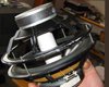
I think he was talking about the same thing that I am thinking of: The mic is placed directly ON the cone. Let me see if I can find a picture somewhere...
Regards
Charles
Regards
Charles
Definetly ON the cone, near the cone it will have a delay.... and ...
On the cone will the resonance of the mic become interesting, this makes faseshifts (rolloff from mic output). It better bee in favor of the stability at low freq end. As the output from the mic is proposjonal to the speed of the membra mooving on the new base (the bass element cone membran). And will bee 0 for low freq, and 0 for any steady speed, so output will bee proposjonal to the rate of change in speed ( Accelerasjon ) .
Outside the cone it will folow the cone speed, but there is a delay... so a new coil with magnet outside the driven gap. It must bee long throw.
Then there is a BIG question left: Is the output of the element movement supose to bee as Accelleration or speed 😕 of the innput signal.
Normal elements have the current sligtly after the voltage 90* an therefore the forse (current) is delayed, hense the delay shuld bee longer and longer as freq is decreased. Acting lika a integrator of force, that makes the movement of cone 😕
At sub frequencies, the time delay is pretty much negligible. Putting the mike right on the cone just makes it a lousy accelerometer- the diaphragm mass is low, so the output may well be dominated by wind noise and the creaking of cone flaxure.
If you want an accelerometer, use an accelerometer. Though I'm using an AD version, which isn't cheap, you can improvise one pretty easily for a lot less money.
If you want an accelerometer, use an accelerometer. Though I'm using an AD version, which isn't cheap, you can improvise one pretty easily for a lot less money.
Putting the mike right on the cone just makes it a lousy accelerometer-
If you mount it sideways you can avoid that (Maybe I wasn't enough clear about that: it has been and is still done within commercially available products).
After all we want the sound pressure to follow the input signal, therefore a device that monitors sound pressure will definitely have advantages over a device that monitors cone acceleration at a specific position of the cone.
Regards
Charles
sideways
Ah. Duhh. Of course. Senior moment.
So who's doing that commercially? And I'd point out that you're still only sampling at one point, though (as with accelerometers), the cone is normally pretty pistonic at subwoofer frequencies, so that's not too terrible an approximation.
Ah. Duhh. Of course. Senior moment.
So who's doing that commercially? And I'd point out that you're still only sampling at one point, though (as with accelerometers), the cone is normally pretty pistonic at subwoofer frequencies, so that's not too terrible an approximation.
And I'd point out that you're still only sampling at one point, though (as with accelerometers),
At very low frequencies I think one can assume that this point is quite large (maybe larger than the driver itself).
The commercial products: An older Model by the German Manufacturer Backes and Mueller (don't remember which one, I already tried to find an old mag with a picture of it for "capslock") and the new Manger subsonice subwoofer.
We even once searched for the patent (within another thread):
http://l2.espacenet.com/espacenet/bnsviewer?CY=ch&LG=en&DB=EPD&PN=DE3429147&ID=DE+++3429147A1+I+
Regards
Charles
phase_accurate said:
This way your MIC will measure acceleration as well (to an unknown extent), so why not mount it sideways as has been done with some B&W speakers and the new Manger sub ?
Regards
Charles
Well, "membrane parallel to the cone movement" describes the same thing, doesn't it?
Electrets being dirt cheap, one could even place several of them all over the cone 🙂
Well, "membrane parallel to the cone movement" describes the same thing, doesn't it?
Indeed !😱
Electrets being dirt cheap, one could even place several of them all over the cone
Above patent is mentioning something like that in order to lower sensitivity to structure-borne noise. One has to pay attention not to increase the cone mass too much .......
Regards
Charles
I like the idea off x-talk canseling too!Although I work in a coherent transient world instead of a steady state world (sine waves) or chaotic world (noise) I am responding to the query for “any comments.”
For me it was a thought-provoking article. In that way the article had value even if I don’t build one of the circuits.
I like the idea of trying to cancel out voice coil cross talk. I am not certain the assumption of a relationship between current flow in the drive coil and cross talk to the sensing coil is valid. If it is, then at system resonance, where feedback might be most useful, almost no cancellation will occur. In a sealed system, the impedance goes high at system resonance, little current will flow and almost no difference voltage will appear across R7. If that is the case, considering the low pass filter knee point of about 100 Hz, then I am uncertain at what operating frequencies the cross talk cancellation circuit will be valuable. From my own experimentation, cross talk at system resonance is not a concern.
Four, I wish the author had better instrumentation available to test his design. Single frequency sine wave testing can be misleading. A matter of author’s choice was involved in choosing photographed sine wave frequencies for the article. Even the student paper on AD’s Web site showed frequency dependent differences in distortion reduction.
Five, I wish we were told how much feedback was actually achieved using the design. Looking at the RTA graphs, you cannot tell. If closed loop feedback is high, then the author has adjusted for the decreased sensitivity.
Six, I wanted to see a “phase” comparison between the drive sine wave and the differentiator output in addition to the comparison between the sensing coil output and the differentiator output. How close is the processed sensing signal to temporally matching the drive voltage and how much mismatch is there between the drive signal and the sensing coil signal? With a complex, broadband signal, a mismatch can produce ripple in the acoustic output that 1/3 octave analysis is unlikely to detect.
In sum, the circuit will work to provide MFB for a woofer, but while the cross talk canceling circuit is a nice idea it may not provide any real benefits. I am also suspect of how the combination differentiator/integrator circuit will work in the transient world. I can’t promise I will ever build and test this circuit, but if I do I will post results to this thread.
Mark
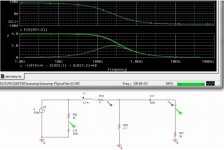
Asum the cone is at standstill.
Then the two coils can bee seen as a transformer with a LR as a low pas filter primary side. With known values.
secondary side is a current sorce loaded with LR.
converting it to the corresponding R/C.
The x-talk seems to have huge effect! lika a bandpass filter that at its maksimum is in phase with input and here normalised it is 6 dB down from drive signal.
Asuming the above is correct: The x-talk maksimum can probably bee generalised as in the middle of the elements passband, ie above fs. having a low Q.
Attachments
There were a subsequent AudioXpress article and comments in letters. They deal with the coils transformer effect and the suggestion to integrate the input signal rather than to differentiate the feedback signal. This is an idea coming from Russel Breden in a similar project described in Electronics World, February 1997, pp104-109.
- Status
- Not open for further replies.
- Home
- Loudspeakers
- Multi-Way
- AudioXpress 11/03 Servo Sub article