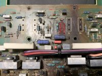
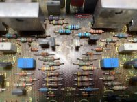
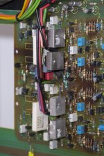
Hello. I want to fix an Audiolab 8000A. It's the PCB version 207 016 Issue 3. Some of the components are completely blown. Close to the transistor 2SC2922 (number 36) is the diode 1N4002 but I cannot identify the values of the 2 resistors. Another resistor is blown close to the ZTX transistor heatsink.
I would be very grateful if anyone can help me to identify these resistors.
Also, a picture of the component and track side of the PCB would help me. This 207 is similar, but not equal to other 207s I have seen. It looks this one is a previous version, because the link between TR35 and TR36 was suppressed modifying slightly the position of the components.
Thanks in advance for your help.
Attachments

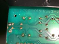
That does not look good, I would think the circuit traces underneath have lifted from the board so you will need to hard wire point to point with wire in some places. If you are not using a turntable then forget about the whole phone section. While the heatsink and output Sankens are out, remove, clean and re-fit with fresh thermal paste and isolator pads if necessary.
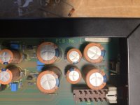
I have an 8000A here which I repaired and modified, swapped out all electrolytic and replaced cooked resistors, it is working and sounding great! Shame these amps are running on the edge of tolerances it seems.
I will PM you and can email the 8000A schematic and service manual with some very good info that should certainly help. If you give me a moment I'll take some pics of the top side and try to get one of the bottom.
Mine is serial number 'D' which is one of the last made in the UK before shifting PCB assembly overseas.
Hello Passive420. Thanks for your answer. Yes I must rebuild some PCB traces and pads. I have the 207 service manual but the PCB drawings are not included. If your amp components layout is like mine, I would appreciate very much some pictures. I will send my email in a private message.
Going just by channel to channel comparison the components missing around transistor 36 are 470R , 100R and 1N4002 . If you take a wider photo than photo No1 I might be able to identify the other burnt component .
PS we have had one of these amps that had blown one element of the ceramic resistors ( 3 legged 2x 0.22 ohm ) . This had also blown protection circuit resistors . By the burning it looks like you may only have one faulty channel .
PS we have had one of these amps that had blown one element of the ceramic resistors ( 3 legged 2x 0.22 ohm ) . This had also blown protection circuit resistors . By the burning it looks like you may only have one faulty channel .
Last edited:
Hello epicyclic. Thanks for your help. I am not sure about that, because the circuit is not symmetrical.
Both channels were faulty. I must replace both 2SC2922. Both blown.
All the pictures I can found, including 207 version, are different with another PCB layout. I have enclosed one sample.
Both channels were faulty. I must replace both 2SC2922. Both blown.
All the pictures I can found, including 207 version, are different with another PCB layout. I have enclosed one sample.
Attachments

The layout is not symmetrical but the protection circuitry and number of components around the output transistors is .
Last edited:
Thanks again for your help. I will take more photos later in order to identify the unknown resistor.
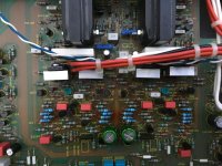
Ok I'll post a few pics here for everyone's benefit but contax will get a few more.
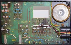
Managed to identify values of the missing resistors - now I think that your amp has been modyfied before, the colour of some of the resistors is different and the remaining blue resistor of the group of three is the wrong value compared to your other channel and mine.
We have a slightly different layout but the values are the same it appears. I have uploaded your pics again with some values noted plus some of mine.
Amongst other things I added a TeddyReg to the pre section and rewired two inputs
Attachments

Last edited:
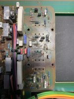
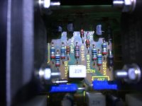
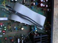
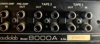
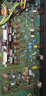
Hello passive420. I have included 3 more pics. Your PCB layout is different, specially between the two 2SC2922 transistors. Furthermore, my amp doesn't have the big flat ribbon cable. I think mine can be older than yours. Mine is serial number 876972.
Your PCB have more 1N4148 diodes between the 2SC2922 transistors. All the pictures I have found have the same layout than your amp.
The blue resistors are new. I have replaced them. These are correct. My PCB has the values marked on the component side.
I have attached a wider image as epicyclic suggested.
Thanks for your help
Attachments

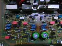
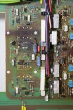
I think passive could be correct with 22R . To confirm I was hoping to be able to identify the resistors on the far right and far left of the driver heat sinks but the latest photos are not quite wide enough . If you would not mind post photos of the right and left hand sides of the driver heatsinks as mentioned . The schematic I am working to shows a 330R resistor between the drivers (one for each channel) but I cant seem to find them on the photos , are they obscured by the wires or hidden at the back of the driver heat sinks or maybe yours are a different value .
Hi @epicyclic. Thanks very much for your interest. I will post new pictures later.
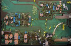
I have seen an old thread and one guy posted a picture with the same layout that my 8000A has
Audiolab 8000A Fault
I have seen an old thread and one guy posted a picture with the same layout that my 8000A has
Audiolab 8000A Fault
This one ?
Its the same around the power transistors but then the layout differs the further you go back into the amp . Good find , the closest yet .
Its the same around the power transistors but then the layout differs the further you go back into the amp . Good find , the closest yet .
Attachments
Last edited:
Yes, it's the closest. These version has two "separated" phono stages, one MM and one MC. The stages don't share the circuit.
I will post more pictures today.
I will post more pictures today.


Yeah, and no Noble volume pot and no 2SK389 JFET input on the power stage. They really improved the build in later models it seems. Shame as the scrap value for the pot and FETs' alone would be nearly £100!
Possibly the FET's are there but separate transistors.
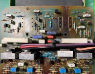
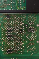
It's hard to suggest anything for the repair in this condition, contax sent me some more pics of the underside and the copper traces around the damaged section are toast, completely gone.
Nothing is impossible though, some careful point to point wiring could get this working. We just need to establish correct values for the resistors. Ideally you would need another 8000A next to you to copy...
Contax - if you are still keen to try then the whole underside needs to be scrubbed with isopropyl first, the flux from flow soldering is clogging the whole circuit and possibly causing bad connections. Then you can hopefully hard wire the new resistors back in.
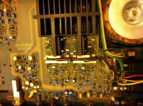
There a a few resistors that need to up-rated to at least 1/2W and raised off the PCB, you might be able to make them out in the fourth photo I uploaded above (bright blue Vishay resistors 1/2W raised, I think 3k9 value)
Possibly the FET's are there but separate transistors.
It's hard to suggest anything for the repair in this condition, contax sent me some more pics of the underside and the copper traces around the damaged section are toast, completely gone.
Nothing is impossible though, some careful point to point wiring could get this working. We just need to establish correct values for the resistors. Ideally you would need another 8000A next to you to copy...
Contax - if you are still keen to try then the whole underside needs to be scrubbed with isopropyl first, the flux from flow soldering is clogging the whole circuit and possibly causing bad connections. Then you can hopefully hard wire the new resistors back in.
There a a few resistors that need to up-rated to at least 1/2W and raised off the PCB, you might be able to make them out in the fourth photo I uploaded above (bright blue Vishay resistors 1/2W raised, I think 3k9 value)
Hello Passive420.
Thanks again for your advice. You’re right. The easiest way would be to have the same version for copying but I cannot find it. I have read on another thread that the original 207 service manual had PCB drawings, but these are not included in the PDF I have.
I also own a Camtech amplifier. It has also the two phono stages but the power stage has the modified layout.
I will continue trying it.

- Home
- Amplifiers
- Solid State
- Audiolab 8000A burnt components