I agree with passive the final missing resistor is 22 ohm .
The circled pink resistor in the photo below looks like brown/black/black/brown 1000 ohms it should be brown/black/black/gold 10 ohms , would you confirm . Maybe the photo colour rendition is not accurate .
The circled pink resistor in the photo below looks like brown/black/black/brown 1000 ohms it should be brown/black/black/gold 10 ohms , would you confirm . Maybe the photo colour rendition is not accurate .
Attachments
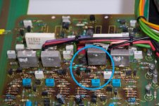
Here is where your early version of the amp has 100 ohm resistors , later models have 47 ohm as listed in the modification box ( top left )
Yes, you're right. My amp is issue 3 and the serial number is 87....
Whith this, the components between the 2SC2922 are clear and I can now rewire some of the blown PCB traces (transistor, diode 1N4002 and 100R)
I agree with passive the final missing resistor is 22 ohm .
The circled pink resistor in the photo below looks like brown/black/black/brown 1000 ohms it should be brown/black/black/gold 10 ohms , would you confirm . Maybe the photo colour rendition is not accurate .
Yes, you'e also right. This resistor was replaced wrongly by me. 10R is marked under it. With the 22ohm all the components are identified.
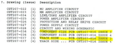
This PCB issue doesn't have the component number only the values. The missing drawings of the original service manual would help very much for rebulding the blown traces.
Attachments
Audiolab 8000A 207 PCB
Hello. Finally, I have got a printer copy of the Audiolab 8000A 207 service manual. This copy includes the PCB layout and would help me rebuilding the blown PCB traces. Thanks for your help!
Hello. Finally, I have got a printer copy of the Audiolab 8000A 207 service manual. This copy includes the PCB layout and would help me rebuilding the blown PCB traces. Thanks for your help!
Attachments
Well done contax, glad you found what you need, hope you get it working.
Looks like you can attach flying leads from the test points to the multimeter, you can then use the trimmers on the top side to adjust bias. Once this is ok I guess you can think about replacing the electrolytic caps.
Looks like you can attach flying leads from the test points to the multimeter, you can then use the trimmers on the top side to adjust bias. Once this is ok I guess you can think about replacing the electrolytic caps.