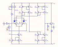
This is a circuit that I think works.
But I have to try it when I get home some more transistors.
It takes 18 of BC560C and BC550C.
It is a VCA. Voltage Controlled Amplifier.
At the input is a divider that divides with roughly 44.
The small resulting voltage is put to input pair.
The current difference is transported to the output, and put across a 10k resistor.
At the output is a buffer transistor.
Max bias input is like 1mA and so is 0.5mA at each transistor.
P2 potentiometer is to regulate the volume with the bias current.
P1 is for adjust eventual output offset.
I might need to adjust some values when I test it at my experimentboard.
Attachments
Lineup,
It has been ten years...................since this thread was active......good to have you back lineup................Mr.Pass probably thinks I am a wildman too. 😀
Jam
It has been ten years...................since this thread was active......good to have you back lineup................Mr.Pass probably thinks I am a wildman too. 😀
Jam
Last edited:
Just for grins and giggles.......................
Attachments
Last edited:
A question for Nelson :
Suppose one builds a balanced version, but the two halves are not 100.0000000% well matched.
i.e. the output of one phase is not exactly -1.000000000x of the other.
Since both current outputs are connected to a single load, where the hell of the difference in the two currents should go to ?
The are absorbed by the net value of impedances at the output:
1) intrinsic output Z of the open loop circuit (always less than infinite)
2) output z due to negative feedback
3) load impedance
Just for grins and giggles.......................
current mirrors are for Sissies

match all transistors to have a Hfe of 200 to 250. Just make sure that all are the same, then the distortion will be lowest.

Is the hFE more important than the b-e voltage?match all transistors to have a Hfe of 200 to 250. Just make sure that all are the same, then the distortion will be lowest.
In this case.
Everyone seems to forget about the Early Effect...............
Eliminating the Early effect in the... (PDF Download Available)
Jam
Eliminating the Early effect in the... (PDF Download Available)
Jam

I dont understand what can be done to eliminate early effect.Everyone seems to forget about the Early Effect...............
Eliminating the Early effect in the... (PDF Download Available)
Jam
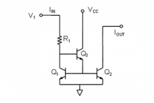
That paper does not say.
It just shows a Wilson current mirror at the end.
An enhanced Wilson (4 transistor goes some way to reduce the Early Effect) but this situation can be reduced further by adding helper transistors (base current compensation). This is particularity helpful if you are using a Widlar Mirror.
Adding resistors to the emitters of the upper mirrors usually helps the accuracy of the mirror.
Cascoding can also help by reducing heating of the mirror transistors.
If you are using transistors of the same lot numbers I find that beta matching is usually less important, besides you could add a trim pot to balance the mirror in a complementary circuit to zero the dc offset, but I digress.......
Jam
Attachments
Last edited:
> If you are using transistors of the same lot numbers I find that beta matching is usually less important,
Do not agree.
I bought recently 200 each 2SC3324BL and 2SA1312BL.
Supposedly already preselected.
hfe is all over the place, and almost no N-P match.
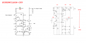
The Pioneer Super Linear Circuit
See PDF in Post#1, also post #127, 132.
> besides you could add a trim pot to balance the mirror in a complementary circuit to zero the dc offset,
For me a must. I have not been able to do without.
But then I also do not have any NFB.
> oh yeah , we know that Jam likes mirrors , current or past , whatever
🙂
Patrick
Do not agree.
I bought recently 200 each 2SC3324BL and 2SA1312BL.
Supposedly already preselected.
hfe is all over the place, and almost no N-P match.
The Pioneer Super Linear Circuit
See PDF in Post#1, also post #127, 132.
> besides you could add a trim pot to balance the mirror in a complementary circuit to zero the dc offset,
For me a must. I have not been able to do without.
But then I also do not have any NFB.
> oh yeah , we know that Jam likes mirrors , current or past , whatever
🙂
Patrick
Hi Patrick,
I have to admit I use feedback in my circuit. I have compared the circuit I use with matched transistors and without and I don't see much difference on the AP
analyzer, maybe a slight reduction in second harmonic but not much else.
I agree that without feedback matching is much more important but if you are direct coupled without a servo you still have to trim dc offset somehow.
I find that matching the input fets I use much more important.
Nice headphone amplifier design.
🙂
Last edited:
- Status
- Not open for further replies.
- Home
- Amplifiers
- Pass Labs
- Audio Virtues of JFET Transconductance Amplifiers