Their front page says they are having material supply problems so i guess they are keeping it all for themselves.I cannot find the information on Edcor.
Cheers
Ian
Don't overlook Magnetostriction as a noise source. it has been a problem on stressed transformers and power inductors for me even when vacuum impregnated and potted. I usually ask for lower flux which means larger cores and larger transformers (and more $$$). Magnetostriction is the steel changing size with the magnetic flux. https://en.wikipedia.org/wiki/Magne...riction (cf.,reaching its saturation value, λ.In power transformers and my experience, noise comes from two main sources:
1. Core laminations or cutting surfaces (c-cores) slamming against each other. C-cores most often need gluing for maximum silence, while EIs might benefit from vacuum potting. This has more often a low-pitched hum (100 to 120Hz), but can result in some higher frequencies buzzing as we..
2. Windings, especially with high pulse current when feeding a high C-input filter. Vacuum lacquer potting helps solving this, but potting does it even better. These often result in a higher frequency buzz.
In my explanations I accentuate more on practical outcome. Noise issue 1. I explained includes magnetostriction as cause.
Dear 50AE!
About output transformer measurements: How to measure stray inductance? How do we calculate the transmission from the measured data and the scattered capacity?
About output transformer measurements: How to measure stray inductance? How do we calculate the transmission from the measured data and the scattered capacity?
To measure leakage inductance you short one winding and then measure the inductance of the other winding.Dear 50AE!
About output transformer measurements: How to measure stray inductance? How do we calculate the transmission from the measured data and the scattered capacity?
Cheers
IAn
Hi there,
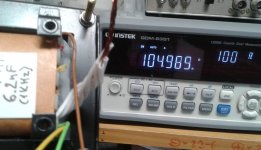
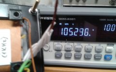
Transformers in practice are a bit complex, so I ditched all LCR meters from my methodology due to values all over the place. Instead I'm measuring shunt capacitance first using a bode plot tracer and changing Rgen value for different cut-offs.
In the past three years I would measure the first HF resonant frequencies and calculate the leakage inductance value, but later I found out it can express itself into different forms.
Transformers form a complex system of LRC circuits. There is a master level of interleaving, where you can hardly excite resonances anymore, because you've distributed them all over the place with smaller amplitudes. Think of how a driver offset works on a baffle. It doesn't kill diffraction, but makes a lot of small diffractions, hence smoother frequency response.
Basically what member @ruffrecords says, but you need to take into account Rdc losses as well. I would load the secondaries with different loads and measure the HF roll-off.
I temporarily stopped measuring leakage inductance due to the various forms of it I have found out I have to study. Leakage inductance can also occur from Rdc differences of windings and it doesn't behave the same way as geometry resulting Ls.
To fight this secondary Ls, one should aim for equal currents circulating across all secondary layers. Some designers use thicker wire for top layers. I just cross-couple layers, so that they become equalized Rdc secondary packages.
Last edited:
- Home
- Amplifiers
- Tubes / Valves
- Audio transformers chat channel.