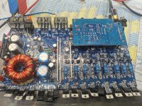
I got this Class A/B Amp, with mosfets.
2 Channels are ok, 2 are disorted.
Outputs and everything else is ok.
The output on the two channels is reduced, and upper and lower sine are disorted.
I expect the mute circuit, but i dont fully understand, how it works.
Attached a diagram from a two channel amp, but its exactly the same:
Page 2: U25A , on the working channel i have a good input sine. Ground from osciloscope is at rca ground.
on the disorted channels, there is no visible input at U25A...
I expect, that the mute circuit is supressing the signal, but i cannot find, where it is suppressed.
Attachments
Its 13VDC, so +6.5 , -6.5V
On each OP amp. So the voltage is ok. Only on this booth channels, the input at this op amp is pulled down..
On each OP amp. So the voltage is ok. Only on this booth channels, the input at this op amp is pulled down..
The input to this op-amp is hard to see because the entire op-amp is floating, isn't it?
Check the power supply pins of the good channels. Isn't there audio on those pins?
Check the power supply pins of the good channels. Isn't there audio on those pins?
First picture is the board.
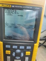
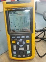
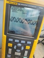
Second the distorted output with gain at full, third is the good output at full gain.
Fourth is pin 7 of the ne5532
Fith picture the same at the good output.
Second the distorted output with gain at full, third is the good output at full gain.
Fourth is pin 7 of the ne5532
Fith picture the same at the good output.
Attachments
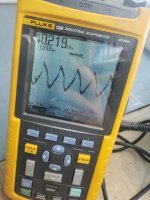
Yes, you are right. On 3 op amps, I have a good signal, also at voltage input. Only the last op amp, from one of the distorted channels has at pin 7 distorted..
If you see the attached pictures, on pin 1,4,7 and 8 I have the sine wave. On the last op at pin 7 it's distorted.
I will test again with ground to rca ground.
If you see the attached pictures, on pin 1,4,7 and 8 I have the sine wave. On the last op at pin 7 it's distorted.
I will test again with ground to rca ground.
Attachments
I think, some measurings are wrong. Iam working on a Ship, and the Electromagnetic Radiation here is very strong, so that it affect my measurings. We have 50Hz Power Plant here aboard.. So if i inject 50Hz Sine...it shows me the Powersupply from our Ship...
If i use sec. center as ground, i have no signale anywhere. Only some Voltage levels. Every second op amp shows me at Pin7 a nearly rectangle Amplitude.
If i use sec. center as ground, i have no signale anywhere. Only some Voltage levels. Every second op amp shows me at Pin7 a nearly rectangle Amplitude.
So, it's the same.. I have sine at each pin..
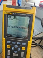
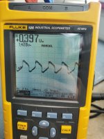
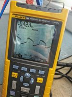
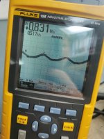
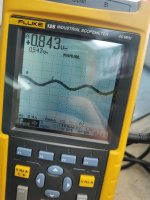
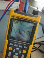
The first picture ist the first distorted channel, the second picture ist the second disorted signal, the third is from a good Chanel. All are pin 7..should be feedback.
The first picture ist the first distorted channel, the second picture ist the second disorted signal, the third is from a good Chanel. All are pin 7..should be feedback.
Attachments
There are signal generator apps for your phone. Use one and use a random frequency that's not a multiple of the mains frequency. Try to keep it between 40 and 100Hz.
Pin 6 is feedback if pin 7 is connected to the 240 ohm resistor to ground.
If you bridge pins 6 and 7, do you get a clean signal on pin 6/7?
This shouldn't cause a problem but be careful when powering up.
If you bridge pins 6 and 7, do you get a clean signal on pin 6/7?
This shouldn't cause a problem but be careful when powering up.
Can you remove the outputs from the channel with the 6/7 bridge to see if the amp will power up without going into protect?
No, still disorted. I can bridge pin 6/7 at the distorted channel now, without going in protect but if it's bridged, the signal disappear
The removed fets are damaged between drain and source.. I don't know, why I couldn't measure this, whit fets inside.
The removed fets are damaged between drain and source.. I don't know, why I couldn't measure this, whit fets inside.
OK. Bridging pins 6/7 was to see if the op-amp and signal reaching it was OK.
Is the amp working now that you replaced the outputs?
Is the amp working now that you replaced the outputs?
- Home
- General Interest
- Car Audio
- Audio System X70.4 Disorted output