Audio System F2 500 MKII fix help
Hi, this is the first amp i'm trying to fix and don't really know what i'm doing so you can slap my face and say i'm wrong.
I know this amp is old and outdated but in the same time i know it's a decent one that can satisfy some nice mids. I would love to fix it instead buying some new cheap amp.
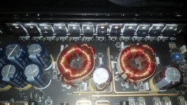
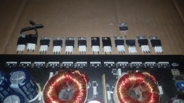
First of all you have to know i have no idea what i'm doing, the problem looks like this. Amp does turn up green light present but there is no sound, from what i've checked the power side mosfets 75333P from Q17 to Q24 are shorted.
Don't really know how to check the gate resistors but with the multimeter set on 200ohm i get some readings on R3 to R10 that vary between 14.3- 19.2 and one of them 56.4
Now i'm trying to check the rectifiers D1 to D4 but i don't really know how to do it.
Unfortunately i couldn't fin a repair manual for this amp but got the F2 190 one that doesn't really help me, even if could find the F2 500 one it would still not help me because i would probably look at it like donkey.
I'm thinking to buy new mosfets and gate resistors to see what happens when i power it up but don't really know what to buy. The closest mosfet i could find to HUF75333P is FQP65N06 and HUF75339P but this one seems to powerfull in my donkey opinion.
Any advice it's welcome
Peace
Hi, this is the first amp i'm trying to fix and don't really know what i'm doing so you can slap my face and say i'm wrong.
I know this amp is old and outdated but in the same time i know it's a decent one that can satisfy some nice mids. I would love to fix it instead buying some new cheap amp.
First of all you have to know i have no idea what i'm doing, the problem looks like this. Amp does turn up green light present but there is no sound, from what i've checked the power side mosfets 75333P from Q17 to Q24 are shorted.
Don't really know how to check the gate resistors but with the multimeter set on 200ohm i get some readings on R3 to R10 that vary between 14.3- 19.2 and one of them 56.4
Now i'm trying to check the rectifiers D1 to D4 but i don't really know how to do it.
Unfortunately i couldn't fin a repair manual for this amp but got the F2 190 one that doesn't really help me, even if could find the F2 500 one it would still not help me because i would probably look at it like donkey.
I'm thinking to buy new mosfets and gate resistors to see what happens when i power it up but don't really know what to buy. The closest mosfet i could find to HUF75333P is FQP65N06 and HUF75339P but this one seems to powerfull in my donkey opinion.
Any advice it's welcome
Peace
Last edited:
IRF3205 is a suitable replacement for the power supply MOSFETs. They're cheap and available. Replace any gate drive resistor more than 10% out of tolerance.
Edit your profile signature to list the equipment you have to work with.
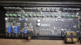
Post a complete photo of the PCB.
Edit your profile signature to list the equipment you have to work with.
Post a complete photo of the PCB.
I've just discovered that the one it show 56 it's actually ok because i could read on the chip 560 rest of them are shorted, am i right about this?
Q22 is falling apart and his R8 is the one that measure 56
Remove the MOSFETS from both banks then test the gate drive resistors.
560 = 56 ohm
I will remove the mosfets tomorrow and measure the gate resistors
Don't really know how to put a signature but this is what i got:
-digital multimeter
-DSO NANO DS210 oscilloscope
-soldering station with hot air gun
Took a while to upload the pictures
Don't really know how to put a signature but this is what i got:
-digital multimeter
-DSO NANO DS210 oscilloscope
-soldering station with hot air gun
Took a while to upload the pictures
Attachments


Excellent. Once you pull the MOSFETs, you can check the rectifiers using diode mode on your DMM. Probes in one direction should read high to infinite. Reverse direction you should have a drop of anywhere from .3 - .8 depending on the rectifier. They rarely fail so I wouldn't expect much. However, if the power supply failed in that manner, I'd expect to test all the output FETs.
Before you fit new MOSFETS in the PS, you'll want to verify the drive is working properly using your DSO and probing each GATE pad of the MOSFETS. You should see a clean square wave. Do not fit the new MOSFETS if you have a drive problem.
Before you fit new MOSFETS in the PS, you'll want to verify the drive is working properly using your DSO and probing each GATE pad of the MOSFETS. You should see a clean square wave. Do not fit the new MOSFETS if you have a drive problem.
I know that having two people helping is generally a disaster but I'm trying to save some time.
Cut Q22 out of the circuit. Then measure the resistance on rest of the PS FETs from leg 1 to leg 2. How many read very low resistance (well below 56 ohms)?
Do you know if that nano scope can display high frequencies?
You'll have to wait until you're out of moderation to edit your sig. Then:
Please (and this applies to anyone who needs repair help) use your sig line to list all equipment you have, editing it as equipment changes. Include the model numbers.
Top of page, menu USER CP >> EDIT SIGNATURE
Oscilloscope (yes or no)
Multimeter(s)
Type of signal source (grounded RCA shields preferred).
Soldering iron
Desoldering pump
Power supply
2 ohm current limiting resistor (hollow cylindrical ceramic 100w preferred)
It's ok I don't mind losing time to check everything especially that I'm a noob, this will make me double check and understand better what I'm actually doing.
I've started to take the mosfets out and the Q22 was the first one, checked the rest of them and they not with us anymore. Hope that is pin1 and pin2 hahaha
I believe the DSO should be able to do the job, it does have quite a lot of setup options
I've started to take the mosfets out and the Q22 was the first one, checked the rest of them and they not with us anymore. Hope that is pin1 and pin2 hahaha
I believe the DSO should be able to do the job, it does have quite a lot of setup options
Attachments

Last edited:
Occasionally, when only one FET fails and there is no sign of burning of the gate resistors or the other FETs, you will have enough FETs to survive to continue testing with the power supply functioning normally. If all of the rest are reading 000 on diode check (the same as when the probes are touching), the other FETs have failed as well.
They are out and readings are like this:
Q17 > Q24 000
D1 .408 >< OL
D2 .408 >< OL
D3 .398 >< OL
D4 .393 >< OL
R3 56.8
R4 57.1
R5 56.8
R6 57
R7 56.8
R8 56.4
R9 57
R10 57
I guess the next step is to get new MOSFETS, if I get the IRF3205 like Matthew mentioned do I have to change the gate resistors to match the new MOSFET?
Q17 > Q24 000
D1 .408 >< OL
D2 .408 >< OL
D3 .398 >< OL
D4 .393 >< OL
R3 56.8
R4 57.1
R5 56.8
R6 57
R7 56.8
R8 56.4
R9 57
R10 57
I guess the next step is to get new MOSFETS, if I get the IRF3205 like Matthew mentioned do I have to change the gate resistors to match the new MOSFET?
Attachments
In my opinion, the 56 ohm are borderline. 47 ohm are commonly used with 3205s.
Do NOT buy semiconductors from ebay or amazon. Buy from a reputable distributor.
Did you check the output transistors? The PS very commonly short 1-2 but the outputs need to be checked from 2-3 at the least. 1-2, 1-3 and 2-3 is more reliable.
Do NOT buy semiconductors from ebay or amazon. Buy from a reputable distributor.
Did you check the output transistors? The PS very commonly short 1-2 but the outputs need to be checked from 2-3 at the least. 1-2, 1-3 and 2-3 is more reliable.
I will buy all the hardware from a good seller not ebay or amazon, i will get 47 ohm cip resistors and IRF3205 this is the list for now.
About the output MOSFETS do i have to take them off the board for a better reading? Because right now with them in place i can't find any that it's blown and when i measure the readings are going up probably charging some capacitors?
About the output MOSFETS do i have to take them off the board for a better reading? Because right now with them in place i can't find any that it's blown and when i measure the readings are going up probably charging some capacitors?
I will buy all the hardware from a good seller not ebay or amazon, i will get 47 ohm cip resistors and IRF3205 this is the list for now.
About the output MOSFETS do i have to take them off the board for a better reading? Because right now with them in place i can't find any that it's blown and when i measure the readings are going up probably charging some capacitors?
You can play it safe and install a single 5a fuse for initial power up.
Will do like that thank you, would be safe to use a car battery as power supply to power it up to check the gate wave with my little oscilloscope? I saw some people using less voltage and less amps for them power supply
If a car battery is all ya got, then it'll have to do. Some amplifiers will switch drive with just remote and GND. You can try that first to avoid charging the primary rail caps. If you see nothing then you'll have to introduce the B+.
But up until you reach the point in the repair where you hear music from that thing, a single 5a fuse is all that should be installed.
You can post photos of your drive signals here if you're unsure what you're looking at.
But up until you reach the point in the repair where you hear music from that thing, a single 5a fuse is all that should be installed.
You can post photos of your drive signals here if you're unsure what you're looking at.
I will wait to get a safer power supply, i don't want to take any chance to burn something else.
For now i'm just confused about buying the items i need, i've been looking for a specialist supplier and found 2 main ones around here. All good at this point they got all sort goodies on their web page and that is the problem they got way to many.
For example the IRF3205 are divided in many other terminations that means different specs for each of them and beside that if i take for example IRF3205PBF and look for it on both websites they got different specs that makes me confused.
And about the gate chip resistor there are a lot of 47 ohm under different names and specs, what should i look for when i check the specs. I mean what spec of the chip resistor makes it compatible with the MOSFET
You're better off looking at data sheets than specs listed on distributor websites. While they are useful, distributors don't always get everything right.
Part suffixes can be tricky and each manufacturer has their own special convention. For example, PBF is the designation for lead free parts manufactured by Infinieon/International Rectifier whereas the same part manufactured by ON Semiconductor would use a suffix of G to indicate the same thing. Other parts will often have a suffix that designates the product packaging, I run into this most frequently with SMD resistors. Your best bet is to look in the data sheet for either a breakdown of the part number or packaging information. Sometimes you have to find a part number explanation document provided by the manufacturer. (If said doc. has a technical name I'd love to know.)
That said, I would still have Perry double check your selected replacement parts as it appears he's willing to do so. If part of your selection is off he can help you adjust course.
I will wait to get a safer power supply, i don't want to take any chance to burn something else.
For now i'm just confused about buying the items i need, i've been looking for a specialist supplier and found 2 main ones around here. All good at this point they got all sort goodies on their web page and that is the problem they got way to many.
For example the IRF3205 are divided in many other terminations that means different specs for each of them and beside that if i take for example IRF3205PBF and look for it on both websites they got different specs that makes me confused.
And about the gate chip resistor there are a lot of 47 ohm under different names and specs, what should i look for when i check the specs. I mean what spec of the chip resistor makes it compatible with the MOSFET
Since the UK is not very far from my country, this might be a good website to order from if you can't find a good supplier.
Reichelt (I always order my IRF3205 there, they have good ones) this shop is placed in germany
Digi-key (a bit more expensive , but also a good thrustable website)
In UK you can order from rs-online without being a official company I saw? They also have original fets and parts.
Last edited:
Yep that's the web page I will buy from, is no point to buy from europe now because of brexit, things are getting complicated around here.
As for the parts I was thinking to get are these
MOSFETS https://uk.rs-online.com/web/p/mosfets/6886829/
Gate chip https://uk.rs-online.com/web/p/surface-mount-fixed-resistors/0566389/
As for the parts I was thinking to get are these
MOSFETS https://uk.rs-online.com/web/p/mosfets/6886829/
Gate chip https://uk.rs-online.com/web/p/surface-mount-fixed-resistors/0566389/
- Home
- General Interest
- Car Audio
- Audio System F2 500 MKII noob trying to fix it