I can't recommend a 10R series resistor in the supply to the LM386 when the load is 8R. Suggest going for something lower, like 1R. Then the supply won't sag so much. Increasing the two 220uFs to 2200uF will help in giving you better bass.
You guys are so awesome it hurts.
Can you explain why more capacitance will bring out the lower frequencies?
Can you explain why more capacitance will bring out the lower frequencies?
Good question - the answer to that's in two parts. The more comonly touted part (one with measurements to support it) is that the series cap to your speaker, together with the speaker being a resistive load, forms a high pass filter. Increasing the series capacitor to the speaker moves the filter's cut-off frequency down, giving a flatter response to lower frequencies. It also gives a flatter group delay down to lower freqs.
The less appreciated aspect, because its subjective is that having more capacitance across the supply reduces low frequency noise on the supply rail. This gives the perception of better bass definition due to less noise.
Whether these effects are noticeable with an 8bit DAC is debatable though but at least its one less thing to worry about when you upgrade to more bits later on.
I would step back an see if the OP needs more info about audio - 8 bits certainly isn't even telephone voice dynamic range - the 8 bit vocal codecs compand to ~12 bits dynamic range
since the mentioned DAC is a memeber of a family that goes to 12 bits I would expect INL, DNL to be very much better than 8 bits - so if there's room for oversampling then dither may help
and I don't see pointers to Nyquist, questions about sample rate, reconstruction filtering - kind of fundamental to go from digital to analog
Eight bits is old, maybe state of the art 30 years ago. I built a few of this type R2R 8 bit DAC for various systems. Wasn't horribly bad and you could tell what tune was playing. I think that is all Sax is shooting for at this stage.
The other question about iPod into stereo, yes just get a patch cord that goes from head phone jack to RCA stereo jacks if that is what your stereo takes.
Most MP3 players, tablets, run off a 1.5V to 3.7V battery ergo their output is in the 0-3V range which is acceptable for most commercial amps and amp kits. There may be odd stuff out there, vacuum tube head phone amp or something, but mostly everything OTC will work. If the output is meant to go into earbuds or headphones, it should work.
Heck, do those micros have PWM pins? Not to get you distracted but it is a direction you may eventually want to go.
Just to pick up on your temporary distraction, I'm not sure about the Microchip offerings, but hard to beat the PWM peripheral functionality of the Infineon XMC4X00 (ARM Cortex M4) range. They're quoting PWM resolution down to 150pS. Lots of promise with these kinds of chips (designed primarily for digital power applications) to roll your own audio DACs 🙂
Back to the scheduled programming...
Back to the scheduled programming...
Oh man. So many responses. You guys are awesome.
abraxalito -
Thanks for explaining both of these points in clear concise terms. I love learning. I'm having a great time reading your responses.
Just to be clear.... 10R means 10 ohms? thanks.
jcx -
There is some jargon here that I can't seem to pull up on google. Please define INL and DNL. Thanks.
ricortes -
Thank you all so much.
abraxalito -
Thanks for explaining both of these points in clear concise terms. I love learning. I'm having a great time reading your responses.
I can't recommend a 10R series resistor in the supply to the LM386 when the load is 8R. Suggest going for something lower, like 1R. Then the supply won't sag so much. Increasing the two 220uFs to 2200uF will help in giving you better bass.
Just to be clear.... 10R means 10 ohms? thanks.
jcx -
The particular DAC I have on hand is the 8-bit version of the part I put in the schematic... sorry for the discrepancy. I'll end up using the 12-bit one in the final project. May even look into one with an I2S bus... but that's a different conversation for a different time.I would step back an see if the OP needs more info about audio - 8 bits certainly isn't even telephone voice dynamic range - the 8 bit vocal codecs compand to ~12 bits dynamic range
since the mentioned DAC is a memeber of a family that goes to 12 bits I would expect INL, DNL to be very much better than 8 bits - so if there's room for oversampling then dither may help
There is some jargon here that I can't seem to pull up on google. Please define INL and DNL. Thanks.
At the beginning of this thread, I just wanted to get a working circuit. Now that I'm moving in the right direction there, please chat with me about reconstruction filtering (I already know about Nyquist and sample rates).and I don't see pointers to Nyquist, questions about sample rate, reconstruction filtering - kind of fundamental to go from digital to analog
ricortes -
Hit the nail on the head. This is my first foray into generating/amplifying audio signals with a microprocessor so I just want something that works. Once I have that down, THEN I will ask about things that work WELL.Eight bits is old, maybe state of the art 30 years ago. I built a few of this type R2R 8 bit DAC for various systems. Wasn't horribly bad and you could tell what tune was playing. I think that is all Sax is shooting for at this stage.
Yes. My micro has a pretty full-featured PWM unit. What are the advantages of using a PWM with an rc-filter versus using a discrete DAC chip? I did think about going in this direction, but I thought that a discrete DAC chip was the slightly more expensive but better-sounding route. Please compare the pros and cons of using PWM versus seperate DAC.Heck, do those micros have PWM pins? Not to get you distracted but it is a direction you may eventually want to go.
Thank you all so much.
150 picoseconds?!?!? HOT DAMN! They've got some very good electrical engineers on staff 😉 I would have to dig through the PIC32 datasheet to tell you what the PWM accuracy is on my micro (too sleepy for that 😛), but if I recall correctly, it's somewhere in the tens-hundreds of nanoseconds.Just to pick up on your temporary distraction, I'm not sure about the Microchip offerings, but hard to beat the PWM peripheral functionality of the Infineon XMC4X00 (ARM Cortex M4) range. They're quoting PWM resolution down to 150pS. Lots of promise with these kinds of chips (designed primarily for digital power applications) to roll your own audio DACs
Back to the scheduled programming...
Last edited:
Thanks for explaining both of these points in clear concise terms. I love learning. I'm having a great time reading your responses.
I'm having a great time fielding your questions - they're a blast of fresh air as so few people on here are asking questions, most think they know a thing or two about audio 😀
Just to be clear.... 10R means 10 ohms? thanks.
Yep, you got it.
btw INL and DNL are specs relevant to DACs and ADCs more in instrumentation applications (i.e. static ones) than in audio. So I doubt you really need to know about these - in audio dynamic specs are more relevant. And the most relevant ones to how they sound aren't quoted much if at all.
Yes. My micro has a pretty full-featured PWM unit. What are the advantages of using a PWM with an rc-filter versus using a discrete DAC chip?
That question is worth a complete thread on its own. Its a much more advanced topic. A big con for the on-chip PWM units is that they're on-chip, meaning you'd need to use some kind of external buffering to reduce noise. Oh, but I forgot for a moment you're only doing 8bits, so probably no you'd be fine at that level. If your PWM unit has 256 or more widths available, it'd be worth a try at the very least.
By buffering do you mean like an op-amp voltage follower? Also, my PIC32 gets about 9.5 bits of PWM accuracy when the PWM period is 44.1 kHz (You would want 44.1kHz PWM period because of the Nyquist effect/sampling rate on audio files, right?)That question is worth a complete thread on its own. Its a much more advanced topic. A big con for the on-chip PWM units is that they're on-chip, meaning you'd need to use some kind of external buffering to reduce noise. Oh, but I forgot for a moment you're only doing 8bits, so probably no you'd be fine at that level. If your PWM unit has 256 or more widths available, it'd be worth a try at the very least.
I'll start up a separate thread about it for the heck of it. Thanks. Are you aware of whether there is a special process for starting a new thread that is a "spin-off" of a previous thread?
No, I meant a digital buffer rather than an analog one. The digital buffer is relatively immune to the noise from the chip and can be provided with nice quiet power supplies so as not to contribute much extra noise itself.
Can the PWM do symmetric (two-sided) modulation? If not I think there's a potential problem that the 'centroid' of the PWM pulse will get later in time wrt to the sample clocks with higher amplitudes. I'd guess this results in some kind of distortion. Yes you'd want 44k1 symbol rate, at least to begin with. Then later you can play around with oversampling and noise shaping if they float your boat.
Not aware of any special process no. Often such threads get titled 'New Title (was 'Original Title')' or something similar.
Ah ok. I understand now.No, I meant a digital buffer rather than an analog one. The digital buffer is relatively immune to the noise from the chip and can be provided with nice quite power supplies so as not to contribute much extra noise itself.
No. It doesn't do two-sided modulation. I'm not sure if this would actually cause a problem or not. Part of me agrees with you but part of me is unsure. We can look for a definitive answer in a new thread.Can the PWM do symmetric (two-sided) modulation? If not I think there's a potential problem that the 'centroid' of the PWM pulse will get later in time wrt to the sample clocks with higher amplitudes. I'd guess this results in some kind of distortion.
Until then, I'll work on putting together something with my existing ADC, audio amp chip, and 8 ohm hobby speaker and report my success. I couldn't get my hands on any 2200 uF caps. The lab was out of em 🙁 I guess I'll just join a handful of 220's in series.
The 2200uF was rather gilding the lily I must admit 😉 - if you use 220uFs be sure to put them in parallel rather than series... 😛
Sorry for the double post... Can't edit my previous post because 30 mins have elapsed since it went up.
Here are two schematics that I've drawn up for the two different situations that I'm interested in. To be explicit:
1. Connect directly to an 8 Ohm 1 Watt hobby speaker
2. Connect DAC out to a very large speaker with built in amplifier.
Tell me if they look right, please!
Too many posts to read all through but there is a problem with the LM386 diagram. Pin 3 needs to be referenced to ground.
Have a look at the applications here,
http://www.ti.com/lit/ds/symlink/lm386.pdf
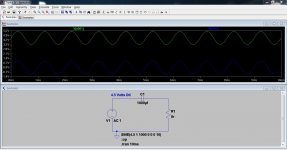
This shows how a cap removes DC and "centres" the audio around zero for the speaker. The top trace is the LM386 output at 4.5 DC with the audio superimposed on that. The lower trace is the voltage across the speaker. The DC is removed and the speaker cone can move in and out centred around zero.
Attachments
So I need to put a 10K pot going from pin 3 to ground?Too many posts to read all through but there is a problem with the LM386 diagram. Pin 3 needs to be referenced to ground.
Have a look at the applications here,
http://www.ti.com/lit/ds/symlink/lm386.pdf
Thanks for posting your SPICE schematic. I can see things more clearly now.
The pot will give you an external volume control, which you probably need tbh. If not then a fixed 10k would be fine.
(The gain of the LM386 circuits is high and you already have more than enough signal from the DAC. You need the pot and probably a series resistor feeding it as well)
(The gain of the LM386 circuits is high and you already have more than enough signal from the DAC. You need the pot and probably a series resistor feeding it as well)
Alright, guys, delivery time.
We're playing a really short snippet of Scott Joplin's "Maple Leaf Rag" here. There is no filetype, it's about 50kB of mono 8-bit raw audio data stored directly in a C-array as hexidecimal values. In the next few days, I'll be adding an SD card, so I will be able to read WHOLE WAV files.
Audio snippet with PIC32 - YouTube
Thank you guys a TON. I have a final exam tomorrow, but once school is done for good, I'll be back (with a 14 or 16-bit DAC) and looking for more tips.
Here's a suggestion for a 16bit DAC to try - Digital to Analog Converter - Precision DAC (=<10MSPS) - DAC8580 - TI.com
The Metrum Octave and Hex DACs I believe use this and get stellar reviews.
The Metrum Octave and Hex DACs I believe use this and get stellar reviews.
It's surface mount... I just have a breadboard 🙁
If you think this one is REALLY worth it, I have the stuff I need to fabricate a homemade PCB and I could make a breakout board for it...
If you think this one is REALLY worth it, I have the stuff I need to fabricate a homemade PCB and I could make a breakout board for it...
Does your MCU have an I2S serial port? If so then you could perhaps set it up to feed a TDA1387. Its also SMT but the pin spacings are more friendly than that TI part. I don't think TDA1387 is a current production chip but there are sellers on eBay for a reasonable price I believe. Needless to say this DAC sounds awesome when done right 🙂
If you really can't face SMT parts, there's always TDA1543 in DIL8.
If you really can't face SMT parts, there's always TDA1543 in DIL8.
Last edited:
- Status
- Not open for further replies.
- Home
- Amplifiers
- Chip Amps
- Audio signals crash course