Hi diyaudio forum,
I'm a firmware engineer, meaning I have a lot of experience programming microprocessors, some experience with digital signals, but almost no experience with analog circuits.
For a new project I'm working on, I need an audio output. I have an mcp4901 DAC and a few opamps. I would like to be able to plug this into the audio in on a large pair of speakers with an integrated amplifier OR a small hobby 8 ohm 1 watt speaker. How much current will be drawn? Do I need to amplify the 0-3.3 volts coming out of the DAC? How would I do so?
I don't want to come in without contributing anything, so if you have ANY questions about microchip PIC microprocessors or Atmel AVR microprocessors, I can help you 😀
Thanks. Y'all are awesome.
Welcome to diyAudio 🙂
OK... you have a signal range of 0 to just over 3 volts from the DAC.
So making some typical assumptions... your speaker with integral amp should have an input sensitivity (amount of signal needed for full output) of way below that figure. Probably nearer 1 volt or less. So what you need for that is a simple volume control to attenuate the 3.3 volts all the way down to zero or if you are using software and controlling the DAC output, a simple fixed attenuator to ensure you don't overdrive the amp.
To connect the DAC to a speaker you need a simple amp. 3.3 volts is plenty loud enough across a speaker but the output from the DAC will be unable to deliver any appreciable current. Something like the LM386 should be OK and is fine with a 9 volt battery as a supply. Stick LM386 into google and you'll find zillions of designs (or ebay ?? if you want one with a PCB)
Finer details would include AC coupling the output from the DAC with a capacitor to block any DC to the input to the amp.
Can we ask whether this is to reproduce music or is it just for electronically generated tones etc
Thank you so much for your speedy and informative response!!... This is why the DIY community is so awesome.
Also, how much current will a speaker like you're imagining draw? microamps, milliamps, or whole amps?
Thanks again!!!!
This is to reproduce music from a format similar to a WAV file that I'm defining. Will be using a PIC32 to read an SD card and send data to the DAC.Can we ask whether this is to reproduce music or is it just for electronically generated tones etc
So... how can I tell what the input sensitivity is? What happens if I feed in a signal that exceeds 1 volt?So making some typical assumptions... your speaker with integral amp should have an input sensitivity (amount of signal needed for full output) of way below that figure. Probably nearer 1 volt or less.
So can I just slap a voltage divider in there with a pot right underneath the second resistor to attenuate the signal?So what you need for that is a simple volume control to attenuate the 3.3 volts all the way down to zero
The mcp4901 is an 8-bit DAC (will use higher quality one in later iterations of the project), if I attenuated the signal from 3.3 to 1 volts in software I would lose about 1.5 bits of signal accuracy. Don't want that!!..... I think there's a similar component with a Vref that I can set to 1v. I'll have to add that to my digikey shopping list.if you are using software and controlling the DAC output, a simple fixed attenuator to ensure you don't overdrive the amp.
Also, how much current will a speaker like you're imagining draw? microamps, milliamps, or whole amps?
Why do I need an LM386 to drive this? Why can't I just use a plain old opamp or even a darlington pair or single transistor?To connect the DAC to a speaker you need a simple amp. 3.3 volts is plenty loud enough across a speaker but the output from the DAC will be unable to deliver any appreciable current. Something like the LM386 should be OK and is fine with a 9 volt battery as a supply. Stick LM386 into google and you'll find zillions of designs (or ebay ?? if you want one with a PCB)
What role does AC play in the speaker's output?? I would think that everything here is DC.Finer details would include AC coupling the output from the DAC with a capacitor to block any DC to the input to the amp.
Thanks again!!!!
Last edited:
The input sensitivity will be quoted by the manufacturer of the amp/speaker combo but its almost certainly going to be 1 volt or less. If you overloaded it by feeding it more than 1 volt (assuming there isn't a volume control already on this "active" speaker") then the audio would be horribly distorted and there is the real danger of damaging the amp/speaker through overload.
Don't worry too much over the sensitivity. Its more a case of add a volume control and see how it performs. If all the action happens in the first few degrees of rotation then you can pad it out with a resistor as you mention.
A small speaker and an LM386 amp would draw tens of milliamps typically on normal audio as I think your intending. We always talk RMS values so 1 watt into 8 ohm requires 2.83 volts RMS.
AC... If you apply 0 to anything DC across a speaker the cone will just move one way. We use a cap to isolate the DC from the amplifier so that the cone can move in and out.
Imagine a sine wave. The amplifier output will be sat at 4.5 volts DC (on a 9 volt battery) and the amplifier can go from 4.5 to 9 and from 4.5 down to 0. Coupling the speaker via a cap removes that DC and the cone can move from 0 to 4.5 and 0 to minus 4.5 with no permanent DC present.
I'll have more time later if you have any questions 🙂
Thanks a bunch for this great info. I understand this situation way more clearly now
When you mentioned AC at first, I automatically thought "wall outlet AC". That makes sense now.
A few questions I still have or that were misunderstood:
1. How much current will a large speaker with a built-in amp draw, NOT a hobby one with an amplifier?
2. Why is an LM386 better than just an opamp, darlington pair, or single transistor? Why won't those things work?
Thanks!
Last edited:
How much current a speaker draws depends on the voltage applied. Lets keep it simple.
1 watt rms into 8 ohms. That's 2.83 volts rms or around 4 volts peak and 8 volts peak to peak. You multiply the RMS value by root 2 to get the peak. So 2.83 volts applied to 8 ohms as looked at on a scope would be an 8 volt peak to peak sinewave. The current would be around 500 milliamps peak in each direction. That is to say 0 to 500ma and 0 to -500ma.
Opamps have very small current ability, typically 20 to 40 milliamps at best. The LM386 is a sort of "power opamp" that can deliver more current. Using separate transistors is fine but you have other problems to contend with. A single transistor can make a simple amplifier but it would have to run in Class A meaning current at least equal to the max current the load would need must flow at all times. Thats wasteful of power. We can use two transistors, an NPN and PNP but now we have the problem that as the signal passes through the zero point there is a dead band (the 0.6 volts vbe of each transistor). We get round that by biasing them both into conduction a little.
A power opamp like the LM386 does all that for you 🙂
Thanks a bunch for this great info. I understand this situation way more clearly now
When you mentioned AC at first, I automatically thought "wall outlet AC". That makes sense now.
A few questions I still have or that were misunderstood:
1. How much current will a large speaker with a built-in amp draw, NOT a hobby one with an amplifier?
2. Why is an LM386 better than just an opamp, darlington pair, or single transistor? Why won't those things work?
Thanks!
How much power do you need for the speakers? Therein lies your current demand.
The lm386 is a good suggestion. I imagine the author was not familiar with your opamp and discrete supply. You could build a discrete amplifier or use your opamps given the meet the specifications of your project.
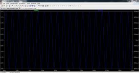
This shows the voltage across an 8 ohm resistor (speaker) when 2.83 volts RMS at 1 kHz is applied. Voltage at the left, current at the right. There are two traces here but being a resistor the current and voltage are in phase so the traces sit on top of each other.
This is from the output of a high power amplifier where the output is sat at around 35 volts DC and coupled to the 8 ohm load via a cap. You can see how the voltage across the load now goes above and below the zero point.
This is from the output of a high power amplifier where the output is sat at around 35 volts DC and coupled to the 8 ohm load via a cap. You can see how the voltage across the load now goes above and below the zero point.
Attachments
Mooly-
Thanks for explaining why an lm386 is necessary. As an absolute beginner with audio and a remedial student with analog electronics, this wasn't immediately obvious.
zymurgn-
I must be phrasing my first question poorly. If I connected my ADC out to the quarter inch jack on a generic speaker with built-in amp like this one, how much current would be drawn? Will just plugging the output of the ADC straight into the input of the speaker be able to provide enough current?
Edit for Mooly's reply with a SPICE sim:
Seeing a graph is great. can you please post a schematic of the circuit that generated this?
Thanks for explaining why an lm386 is necessary. As an absolute beginner with audio and a remedial student with analog electronics, this wasn't immediately obvious.
zymurgn-
I need to learn more about how an amp functions and how much current opamps can provide before I can do this stuff 🙂. I'm coming here knowing practically nothing about amplifying audio signals.The lm386 is a good suggestion. I imagine the author was not familiar with your opamp and discrete supply. You could build a discrete amplifier or use your opamps given the meet the specifications of your project.
I must be phrasing my first question poorly. If I connected my ADC out to the quarter inch jack on a generic speaker with built-in amp like this one, how much current would be drawn? Will just plugging the output of the ADC straight into the input of the speaker be able to provide enough current?
Edit for Mooly's reply with a SPICE sim:
Seeing a graph is great. can you please post a schematic of the circuit that generated this?
Last edited:
OK... the amplifier input (that's the amplifier built into that speaker) will draw very little current from the DAC output. How much is impossible to say without seeing the circuitry but it will probably present as something like a 10k load so absolutely no problem for any opamp to drive such as the DAC output might use.
I'm about done for tonight but just to clarify as you are delving into the hardware side of things at the DAC....
A normal DAC output (that a customer would buy and use) will have the audio output either capacitor coupled to remove DC or the DAC output will be DC coupled but with the output centred on zero volts.
If you are working with the hardware itself then be aware that the DAC output (on the pins of the IC) may well be at some DC voltage and that must be blocked with a cap.
If your using proprietary outputs there is no problem, if your poking about on the chips themselves then there could be a DC problem.
Ok.. That's what I thought. Thanks...OK... the amplifier input (that's the amplifier built into that speaker) will draw very little current from the DAC output. How much is impossible to say without seeing the circuitry but it will probably present as something like a 10k load so absolutely no problem for any opamp to drive such as the DAC output might use.
Just to be clear, I'm constructing a circuit from scratch. I have my 8-pin DIP DAC's in a drawer and my LM386N-1's in a drawer and I'm going to put them on a bread board. What exactly do you mean when you say that the dc voltage must be blocked with a cap... Are you saying that I need to put a cap on the output pin of the DAC? How will that center the voltage around 0?
The voltage of the DAC will be between 0 and 3.3 volts. Like we said earlier, if I'm hooking up to a larger speaker, I'll use a voltage divider to bring it to 0-1 volts. I'm I'm driving a small speaker directly, I will leave it at the full 0-3.3 volts and send the output to an LM386.
Thanks for all your help. Have a good night. Seeing as I'm in the United States, I have a few more daylight hours and will start poking and prodding. I'll let you know how things turn out.
Last edited:
99% sure that particular powered speaker would have caps on the input so you could drive it directly from your DAC. Like Mooly says, you really need the schematic to tell. That 1% would be a $210.89 mistake so you can see why Mooly is cautious.
I gave the DAC data sheet a quick glance. It looks like it has a built in op amp capable of delivering ~25 mamps. It also has a voltage ref pin to set the output range.
Of course you can tackle it anyway you feel like. If it was me, I would set the output to be in the range of 0-1.5 volts max which will depend on what voltage you are running the system at. This would be a bit of overkill in that most audio power amplifiers are set up to be driven at full power output at .7V to 1V.
You may want to consider something like driving headphones directly from the circuit. In that case it should be capacitively coupled to the head phones, maybe a 10 uF cap would do it. Should be able to put out ~100 mWatt which is pretty much uncomfortably loud for headphones. I am terminally cheap so blowing out a set $1 earbuds appeals to me more then a $200 stereo.
So how can I take my ipod and plug it into an arbitrary speaker with a built-in amp? Does the iPod just never output more than 1 volt or something?99% sure that particular powered speaker would have caps on the input so you could drive it directly from your DAC. Like Mooly says, you really need the schematic to tell. That 1% would be a $210.89 mistake so you can see why Mooly is cautious.
Yeah. I will probably supply vref with a voltage divider and give it 1 volt. This will be adjustable with a pot.I gave the DAC data sheet a quick glance. It looks like it has a built in op amp capable of delivering ~25 mamps. It also has a voltage ref pin to set the output range.
If I capacitively couple to headphones, can I use a polarized cap?
I'll post some schematics of what I have in mind in a few minutes...
Or not. Trying to get microchip parts in my schematic is going to give me an aneurysm. I can't believe that a huge company like Microchip is incapable of providing a good Eagle library.
Last edited:
The nearly infinite versatility of the Microchip microcontrollers means that most ports are used differently in each project. Consequently, I usually create a new schematic symbol for each project, locating the various port pins at different locations on the uC "block" symbol to make the completed schematic more readable, based on how the port pins are used in a particular project.. . . . I can't believe that a huge company like Microchip is incapable of providing a good Eagle library.
Dale
The nearly infinite versatility of the Microchip microcontrollers means that most ports are used differently in each project. Consequently, I usually create a new schematic symbol for each project, locating the various port pins at different locations on the uC "block" symbol to make the completed schematic more readable, based on how the port pins are used in a particular project.
Dale
That's true, but the microchip part I'm looking for is a simple SPI interface DAC. It only has 8 pins, so what you're saying shouldn't be a problem.
Consider the idea in Post #3291 in the "Low-distortion Audio-range Oscillator" thread at http://www.diyaudio.com/forums/equi...n-audio-range-oscillator-330.html#post3739621 , and the follow-up posts #3295 thru 3299 (especially #3298). Is there a PIC processor that can put itself into a deep sleep (no clocks) mode, but be awakened by, say, a long-duration logic level change (either LO or HI) on some pin? I know that some of the LIN bus-compatible UARTS would generate interrupts in response to a BREAK state on their receive line, but I don't think they would do it with no clocks on the chip.. . . I don't want to come in without contributing anything, so if you have ANY questions about microchip PIC microprocessors . . .
Dale
Oops! I skimmed thru the thread too quickly to see you were referring to the symbol for a simple DAC. When I see "Microchip" I automatically think "microcontrollers". They DO make DAC's, serial EEPROMS, regulators, opamps, and other useful stuff.That's true, but the microchip part I'm looking for is a simple SPI interface DAC. It only has 8 pins, so what you're saying shouldn't be a problem.
Dale
Hi,
Hard to make any sensible sense of this thread.
An 8bit linear DAC is worse sound quality than basic telephony.
rgds, sreten.
No way should you attempt to use short circuit current levels.
Hard to make any sensible sense of this thread.
An 8bit linear DAC is worse sound quality than basic telephony.
rgds, sreten.
No way should you attempt to use short circuit current levels.
Last edited:
Consider the idea in Post #3291 in the "Low-distortion Audio-range Oscillator" thread at http://www.diyaudio.com/forums/equi...n-audio-range-oscillator-330.html#post3739621 , and the follow-up posts #3295 thru 3299 (especially #3298). Is there a PIC processor that can put itself into a deep sleep (no clocks) mode, but be awakened by, say, a long-duration logic level change (either LO or HI) on some pin? I know that some of the LIN bus-compatible UARTS would generate interrupts in response to a BREAK state on their receive line, but I don't think they would do it with no clocks on the chip.
Dale
I wish I could reply in the corresponding thread, but it looks like those posts are long buried.
I believe that deep sleep can be exited if MCLR is pulled low, thereby resetting the device. Leaving deep sleep is almost identical to a system reset no matter how you go about it, so it's not like railing MCLR while in deep sleep will make you lose anything that wasn't already lost.
No offense intended, but a PM about this would have been nice... I don't want my first thread here to get derailed!
Hard to make any sensible sense of this thread.
An 8bit linear DAC is worse sound quality than basic telephony.
Hi Sreten. Sorry if the thread is hard to follow. I am coming here asking for advice on how to condition the output of an 8-bit DAC to be played through either
1. A large commerical speaker with a built-in amp
or
2. A small hobby speaker (about 8 ohms 1 watt).
I know an 8-bit DAC isn't that great, but it's all I have on hand now. Once I have something simple running, I will improve it with a 14-or-16-bit DAC.
Last edited:
Sorry for the double post... Can't edit my previous post because 30 mins have elapsed since it went up.
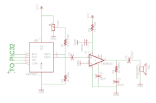
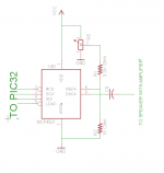
Here are two schematics that I've drawn up for the two different situations that I'm interested in. To be explicit:
1. Connect directly to an 8 Ohm 1 Watt hobby speaker
2. Connect DAC out to a very large speaker with built in amplifier.
Tell me if they look right, please!
Here are two schematics that I've drawn up for the two different situations that I'm interested in. To be explicit:
1. Connect directly to an 8 Ohm 1 Watt hobby speaker
2. Connect DAC out to a very large speaker with built in amplifier.
Tell me if they look right, please!
Attachments
- Status
- Not open for further replies.
- Home
- Amplifiers
- Chip Amps
- Audio signals crash course