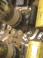
Good thing they put those labels on and taped up the power transformer. The underside of the PCB also seems to be missing some capacitors.
Have you ever seen the wiring that ARC originally used for the output wiring? It's really high quality and quite substantial. I cannot imagine anyone thinking that they could improve upon it. It is because of the gauge of the wire and the difficulty of working with it that I have yet to replace the output barriers on my D76A & D70.
Have you ever seen the wiring that ARC originally used for the output wiring? It's really high quality and quite substantial. I cannot imagine anyone thinking that they could improve upon it. It is because of the gauge of the wire and the difficulty of working with it that I have yet to replace the output barriers on my D76A & D70.
Last edited:

This is what the underside of an original D70 MKII looks like, care of the ARC Database. The wiring shown is identical to mine;

I have been servicing Audio Research Corporation products since the 1970's, so I remember them as they were originally built.
Can't remember what I had for breakfast anymore, but I've never forgotten a piece of equipment🙂
Here's a pic of a D115 MKII underside, also original, care of Ski Fi audio. Never measured it, but I gotta tell ya, that wire is heavy gauge, and they used the same stuff for the inputs as well;
EDIT; Note all of those lovely Rel-Caps. These were always my capacitor of choice.
Good thing they put those labels on and taped up the power transformer. The underside of the PCB also seems to be missing some capacitors.
Have you ever seen the wiring that ARC originally used for the output wiring? It's really high quality and quite substantial. I cannot imagine anyone thinking that they could improve upon it. It is because of the gauge of the wire and the difficulty of working with it that I have yet to replace the output barriers on my D76A & D70.
I had them put two five way binding posts on each channel. The ground is soldered to the ground strip barrier. The other is a jumper that I can choose to select the desired output. At one point I was thinking of replacing the barrier strip but it simply wasn't worth it ripping into the amp.
It works fine, why change it.
Eventually I did get some of them solid brass block space to banana female adapters but I didn't bother using them in this amp.
Those are definitely not original. I believe those are the original Pearl Iso-Sockets. That's something you don't see every day!
https://pearl-hifi.com/03_Prod_Serv/Kits_Parts/Iso_Sockets/Iso-socket_Install.pdf
https://pearl-hifi.com/03_Prod_Serv/Kits_Parts/Iso_Sockets/Iso-socket_Install.pdf
Do you still need pictures of my amp?
I fell yesterday and hit my backside... so lifting amps today is gonna be a painful affair. Sorry.
I fell yesterday and hit my backside... so lifting amps today is gonna be a painful affair. Sorry.
Today I replaced all semiconductors within the 327V regulator. It now measures spot-on at the correct voltage. Continue to see the noise at the output, however.
Okay now that all the DC voltages have been stabilized and measure correctly, I have been able to zero in on the remaining issue. It appears the source of the noise is an oscillating V13, the 12AX7. Audioking have you encountered this in your travels with these amps?
I note that mine has RF chokes in series with the cathodes that do not appear on the schematic. Also, I think there is an error on the schematic as the cathode voltage shows as 15 Volts, but there is in fact, a 6.2V zener tied to ground.
I note that mine has RF chokes in series with the cathodes that do not appear on the schematic. Also, I think there is an error on the schematic as the cathode voltage shows as 15 Volts, but there is in fact, a 6.2V zener tied to ground.
The Zener is correct. Don't forget, that portion of the circuit is fed from a stacked supply.
RF chokes from which cathodes to ground? Other than the transformers and the relay, there are no other coils used in this amplifier.
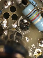
Unfortunately, your amp looks like it's been subjected to some serious mucking about. You're going to have to get some very good closeup pics of original units and start comparing what's what on your board.
There are a lot of low value capacitors throughout the power supplies, and they are all critical and necessary for proper operation. I'm guessing some will be missing.
RF chokes from which cathodes to ground? Other than the transformers and the relay, there are no other coils used in this amplifier.
Unfortunately, your amp looks like it's been subjected to some serious mucking about. You're going to have to get some very good closeup pics of original units and start comparing what's what on your board.
There are a lot of low value capacitors throughout the power supplies, and they are all critical and necessary for proper operation. I'm guessing some will be missing.
Thanks, yes - it has been seriously mucked with. The chokes are connected in series with each of the cathodes of V13, the 12AX7.
Correction: My bad, the chokes are in series with the grids, not the cathodes!
Correction: My bad, the chokes are in series with the grids, not the cathodes!
Last edited:
I can't imagine that an extra inch of wire from the socket would induce instability.
At this point, I believe that you are going to have to invest a significant amount of time and effort analyzing this unit and putting everything back as designed. Trying to troubleshoot this amplifier "as is" will be nothing more than a very frustrating exercise in futility. You need to go over everything.
As an aside, I will not accept any Audio Research product for service that has been modified. I no longer have the patience for undoing other peoples technical fantasies😒
Agreed. I want to have the DC operating parameters within spec and operating quietly first. Then along with some fresh tubes, I can drill down into the amplifier itself. It’s keeping this retiree occupied.
Audio King, after rebuilding three of the four discrete voltage regulators, plus replacing all of the 9 pin tube sockets and every electrolytic cap, I needed to take a break and do some listening, even though there is still some noise that’s slightly audible and impacting THD measurements.
I get your comments about your ARC addiction and that the REL caps are remarkable after forty some years!
I get your comments about your ARC addiction and that the REL caps are remarkable after forty some years!
One of the areas that has proven to be problematic with this era of ARC power amps are the bias and balance trimmers. Like any control that doesn't see much action, they go noisy over time. The AC balance pots are usually the culprits due to the higher current flow.
I have occasionally been able to clean them (You can probe them with a signal tracer or scope to find the noisy one) but replacement is always my preferred course of action. Not everybody wants to open their wallet that far though...
EDIT; My own (very much later) VS110 has developed a couple of noisy octal sockets. I will be replacing all eight, and I'll probably do the 9-pins at the same time. The Belton PCB mount types are excellent quality, very reasonably priced, and are direct drop-ins.
Last edited:
You mean, VT100?
That's certainly one of the amps I want... the VT100 Mk II. It has balanced inputs.
For many years I wanted the VT200 and then one day I saw it for real... I put my hands on it. It makes the A2s in their 5U, 400mm cases seem puny. That sucker is HUGE.
OK, back to the D70 MkII. Right now it's in the rack, on the "in case of amp fire break glass" shelves. I keep telling myself that one of these days I got to use the damn thing!
BTW, are output tubes hard to get nowadays? When I redid my D70 early last year the guy had only two quad sets of Svetlanas left. So, I was pretty lucky. Similarly, I got one of the last Russkie tube sets from the factory for my CJ PV9.
- Home
- Amplifiers
- Tubes / Valves
- Audio Research D70 MKII