Self s lin monoculture has an advantage , though , just look at the japanese production from late 70s to early 80s and you
can be sure to see all his past, present and future iterations
of this ubiquitous design.
Crashingly wrong, I'm afraid. The Blameless amplifier has three stages, and the Lin configuration two stages. They are quite different.
See Fig 30.5 in my book.
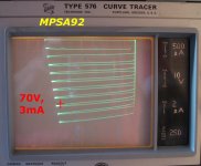
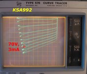
I popped an MPSA92 (rated 300V) and a KSA992 (rated 120V) into the curve tracer and took a look. Regrettably, self-heating caused quite a bit of trace looping: 70 volts x 3 mA = 210 milliwatts, in a plastic TO92. The usual fix (set Polaroid camera on infinite exposure, turn off graticule, and use "DC" sweeping) couldn't be applied since I don't own a Polaroid camera! I've got a cheap Canon digital, which I don't know how to set to infinite exposure. Sorry for the loops.
I marked the 3 mA point since that's where each of the IPS devices are biased when the tail current is 6 mA, per D. Self's recommendations (6th ed, p.135)
This KSA992 had a beta of about 700 (Ic=3mA / Ib=4.2uA) while the MPSA92 had a beta of about 200 (Ic=3mA / Ib=15uA).
More significantly, the MPSA92 had outstandingly high output impedance; a/k/a enormous Early voltage. The KSA992's output impedance was disappointingly low; extrapolating the curves suggests a VA of only ~ 100 volts or thereabouts. P. U. pew
Which may suggest using the MPSA92 as a cascode device, and a lower voltage, high beta transistor for the long tailed pair "within the protective envelope of the cascode". Perhaps the BC327, or the 2N4250A, or the 2SA970 would be good choices.
n.b the 970 is still available from B&D Enterprises. I bought 50 of them, two weeks ago, and they appear to be genuine.
Attachments
It is true that the input transistors are not at all critical. High beta is good as it reduces voltage offsets and input current distortion. (but you should always drive from a low impedance to prevent the latter being a problem anyway)
Noise is also not critical, in the sense that the amplifier with ordinary transistors (eg MPSA56) is quieter than almost any stage you can put in front of it.
That is reassuring as it looks soon to be Hobson's choice .
I think I will by myself a stock of .
2N5551 / 5401
MPSA 92 / 42
BF 720 / 721 .
BC 550 / 560 ( C , too late ? )
MJE 340 / 340
BD139/140
BCV61/62 .
I have some 2SD 756 . At a gain of 130 I think they must be fakes ( 2N5551 perhaps ) .
I popped an MPSA92 (rated 300V) and a KSA992 (rated 120V) into the curve tracer and took a look. Regrettably, self-heating caused quite a bit of trace looping: 70 volts x 3 mA = 210 milliwatts, in a plastic TO92. The usual fix (set Polaroid camera on infinite exposure, turn off graticule, and use "DC" sweeping) couldn't be applied since I don't own a Polaroid camera! I've got a cheap Canon digital, which I don't know how to set to infinite exposure. Sorry for the loops.
I marked the 3 mA point since that's where each of the IPS devices are biased when the tail current is 6 mA, per D. Self's recommendations (6th ed, p.135)
This KSA992 had a beta of about 700 (Ic=3mA / Ib=4.2uA) while the MPSA92 had a beta of about 200 (Ic=3mA / Ib=15uA).
More significantly, the MPSA92 had outstandingly high output impedance; a/k/a enormous Early voltage. The KSA992's output impedance was disappointingly low; extrapolating the curves suggests a VA of only ~ 100 volts or thereabouts. P. U. pew
Which may suggest using the MPSA92 as a cascode device, and a lower voltage, high beta transistor for the long tailed pair "within the protective envelope of the cascode". Perhaps the BC327, or the 2N4250A, or the 2SA970 would be good choices.
n.b the 970 is still available from B&D Enterprises. I bought 50 of them, two weeks ago, and they appear to be genuine.
I value that . Thank you . I use BC327/337 a lot . 2SA 970 is a nice device , a modern high voltage 2N4403 . I do like cascodes . They look like they should be trouble and seldom are . 2SC2240 at 50 for $20 seem better value as UK price is about $1.7 for 970's ( no idea how they compare ) .
A question . What is the optimum matching between LTP and VAS input ? Is it low impedance feeding higher . Higher impedance feeding lower , or as equal as is possible ? I have always assumed a Darlington VAS sidesteps the issue . The Complimentary feedback pair VAS has few supporters . Strange as it seems it should be the best . I have had no problems with CfbP as a VAS . I sometimes think a Darlington helps the current mirror that might precede it . That is the base sits at about 1.2 V rather than 0.6 V . That gives a healthy 1V distance above the Vce of the mirror . It might allow a bit of RC filtering to the rail even . Putting a diode in the emitter of the single VAS seems to be the worst idea ( Goodmans 80 ) . Darlington has other advatages as said previously .
Going back to my question . I feel by observation low feeding high is ideal . I saw in the ESP ( Rod Elliot ) 10 K feeding a VAS running 1 mA ( op amp ) . That seemed impossibly high . It reminded me of JLH and others . He measured - 92 dB 1/3 harmonic and IM at - 72 dB . Made me wonder if squashing the input is such a bad idea . Like the old DIN current fed ( 1 mA / K was it ) idea it might be OK ? Could it be the equal impedance is where it gets vague ? I don't think I have read anything on this .
Going back to my question . I feel by observation low feeding high is ideal . I saw in the ESP ( Rod Elliot ) 10 K feeding a VAS running 1 mA ( op amp ) . That seemed impossibly high . It reminded me of JLH and others . He measured - 92 dB 1/3 harmonic and IM at - 72 dB . Made me wonder if squashing the input is such a bad idea . Like the old DIN current fed ( 1 mA / K was it ) idea it might be OK ? Could it be the equal impedance is where it gets vague ? I don't think I have read anything on this .
Nigel, can you post a circuit where you have done this? I've got problems envisaging how this is done.The Complimentary feedback pair VAS has few supporters . Strange as it seems it should be the best . I have had no problems with CfbP as a VAS
In most Blameless type topologies, the intention is high, IPS + CM, feeding 'low', the VAS.I feel by observation low feeding high is ideal . ... Could it be the equal impedance is where it gets vague ?
I posted some stuff in one of the interminable VAS/TIS arguments suggesting that it should be whether undistorted input (V or I) gives undistorted output (V or I) which determines what it is. I make this distinction, not for stupid semantic pedantic reasons .. but cos it highlights important remaining distortion mechanisms.
The results show that for most Blameless type topologies .. its vague 🙂
Douglas, in your book you state at least twice that output stage distortion is still the remaining unsolved problem in Class-B/AB amplifiers.
Anyone reading your book in isolation would be inclined to think the same thing.
This, fortunately, is not true: M. Hawksford (and later demonstrated by R. Cordell and B. Candy) using feedback error correction virtually solved this "problem" at least thirty years ago. Your book, unfortunately, does not do feedback error correction justice.
Moreover, as far as Class-D is concerned, it would appear you're way out of the loop as Bruno Putzeys at Hypex electronics seems to have achieved less than 7ppm THD across the audio band (400W into 4 Ohms) with his NCore amplifiers:
Hypex Electronics BV - NC400
More info. in respect of applications:
http://www.grimmaudio.com/hifi_loudspeakers_ls1.htm
Last edited:
Nigel, can you post a circuit where you have done this? I've got problems envisaging how this is done.
This is all I have with measurements . It's a bit of fun in the style of JLH . I was able to simplify it and get 50 kHz - 60 dB 8 W . It nicely runs into class AB above that . I also got DC offset to be as good as a LTP amp as does JLH . Forgive this example, it wasn't made for showing here . In the end I used a high beta transistor and more drive current . I hope this qualifies ? It seemed to have high gain and 0.6 V base voltage as would be expected . I did it some time ago . Doubtless I haven't checked all of the connections / voltages . With the same at the input is would have been quite linear .

Nigel Peason,
Your VAS (2N5551 - 1 kOhm - BD 136) is not as Sziklai.
To be it, the 2N5551 emitter should control the current trough a resistor in the collector of BD136.
Here, the 1 kOhm is only submitted to a bootstrap effect by the base-emitter voltage of the BD136.
I've sometimes met a Sziklai used as a VAS but never seen it seriously discussed.
Bruno Putzeys at Hypex electronics seems to have achieved less than 7ppm THD across the audio band (400W into 4 Ohms) with his NCore amplifiers:
Hypex Electronics BV - NC400
If you really take a look at those specs, we might all as well close up shop. Really, this thing runs circles around any amplifier I know of, irrespective of class. Luckily enough, I do audio design because I think it is fun. 😉
jan
 no sooner has the thread reopened and personal attacks happened....guys can't you just discuss the technical merits of your ideas?
Moreover, as far as Class-D is concerned, it would appear you're way out of the loop as Bruno Putzeys at Hypex electronics seems to have achieved less than 7ppm THD across the audio band (400W into 4 Ohms) with his NCore amplifiers:
Hypex Electronics BV - NC400
More info. in respect of applications:
Grimm Audio - LS1
Give attention to the bolded part of your post and its technical significance.
Also , the numbers provided by your latter link :
http://www.hypex.nl/docs/papers/ncore wp.pdf
Nigel Peason,
Your VAS (2N5551 - 1 kOhm - BD 136) is not as Sziklai.
To be it, the 2N5551 emitter should control the current trough a resistor in the collector of BD136.
Here, the 1 kOhm is only submitted to a bootstrap effect by the base-emitter voltage of the BD136.
I've sometimes met a Sziklai used as a VAS but never seen it seriously discussed.
Good point . It worked nicely and gave what I wanted . If you get a better one please post .
It seems a worthwhile debate CfbP VAS .
I do get the impression that the simplicity of the blameless concept is almost rejected for it's simplicity by many . I think such arguments are about moving the spotlight from one person to another more than audible truth . I get very bored with that . I only want answers . I think in olden times it was asked how many angels could dance on a pin head ? Only recently I discovered it was a serious concept in those days ! Ironically Quantum physics started with such mad ideas .
My person concept is at what power level and frequency is - 60 dB unavailable . I stretch to - 40 dB if not suffering high harmonics .
Crashingly wrong, I'm afraid. The Blameless amplifier has three stages, and the Lin configuration two stages. They are quite different.
See Fig 30.5 in my book.
By lin i suggested the single LTP + VAS + OPS configuration
wich is the base of most 70s op amps and consequently
of audio power amplifiers from the mid 70s to these days.
Here is I suspect where I took what I thought to be Sziklai pair and graft it into the VAS . He gives measurements for the input pair ( or single really as it is feedback locked ) that seem convincing . Apart from the 1R5 mine is the same ? This amp is an interesting design . He mentions H C Lin .
Some advanced power transistors are multiple devices . If we were sold a ready made Sziklai pair would we ever know without being told ? We can buy ready made Darlington , why not Sziklai ?
There was a long debate about current feedback . Never once did anyone come up with a design for those wanting to learn . This one is another blameless amp that looks to be valid . I have all the bits , I must build one to compare with the Hitachi / Goldmund .
MJR7-Mk5 Mosfet Power Amplifier Design Notes
http://www.renardson-audio.com/ip-dist.html
Last edited:
By lin i suggested the single LTP + VAS + OPS configuration
wich is the base of most 70s op amps and consequently
of audio power amplifiers from the mid 70s to these days.
If you read the personal history of H C Lin he says he was allowed to release the results of his military work as the early op amps did not meet the criteria laid down . One might guess the blameless layout is H C Lin also . The earliest op amps resembled the Hitachi double VAS . Motorola MC1530 is interesting . The Linn Valhalla had a passing resemblance to it in the output stage . Perhaps to use the high voltage NPN transistors . Earliest blameless amp I find is Sinclair Z30 of 1969 . As said before Gogny of 1967 also is virtually it . Like Apes and Monkeys it is right to think them similar Lin and blameless . I have to build a high voltage amp soon . Maybe the MC1530 should be up-scaled ? If I remember the designer was not popular and was airbrushed out of history . The 741 seems to be the chosen reference point .
http://www.analog-innovations.com/SED/MC1530-TeachingExercise.pdf
Found him . Jim Thompson . Well worth a read as that op amp for a preamp still is valid . 1963 !! I really must try one . I think it is still made by Lansdale ? All NPN is intriguing . H C Lin does say IC and PNP were not easy . If memory is correct an RFA officer engineer asked a question when silicon was being discussed in 1955 at an engineering conference ? He asked would it not be prudent to work out how to use an integrated circuit rather than cut it up and then joined together again when in little cans . I think he argued many circuits repeat themselves ( like an ECC 83 in valves ) . It frustrates me I can't buy the Hitach as a block . LM 4702 is close . The MC 1530 is 8 years after the RAF man and a practical example of his idea being that all are NPN , that would be a logical jump from many NPN to a workable device . Remember valves are all N channel so a familiar world back then .
https://groups.google.com/forum/#!msg/sci.electronics.design/WNk4P54SHaw/2LYLN1RZ4CsJ
Computer History Museum - The Silicon Engine | 1964 - The First Widely-Used Analog Integrated Circuit is Introduced
Oral History Lin Page4 RCA Germanium Transistors Audio
http://www.mtech.umd.edu/news/news_story.php?id=5663
Last edited:
Extract of H C Lin above .
Next, I went to Westinghouse for 10 years, which I think were my best years in industry. This was because Westinghouse and TI were the first to believe in integrated circuits. I joined Westinghouse in 1959, and at that time, to work on an integrated circuit was a “laughing stock”
Next, I went to Westinghouse for 10 years, which I think were my best years in industry. This was because Westinghouse and TI were the first to believe in integrated circuits. I joined Westinghouse in 1959, and at that time, to work on an integrated circuit was a “laughing stock”
Extract of H C Lin above .
Next, I went to Westinghouse for 10 years, which I think were my best years in industry. This was because Westinghouse and TI were the first to believe in integrated circuits. I joined Westinghouse in 1959, and at that time, to work on an integrated circuit was a “laughing stock”
Thanks for the links posted, I found them very interesting. Being of a younger generation virtually none of this info is even mentioned at varsity level which I feel is a pity as much is to be learned from the past to better the future.
As for CFP vas there was more than one commercial manufacturer that used this scheme, I will dig up some schematics although Im not sure whether its legal to post. A beta enhanced vas performs appreciably better and probably the reason one doesnt see CFP much. CFPs have a stability caveat which is probably the reason they were never manufactured as a intergrated part.
Good point . It worked nicely and gave what I wanted . If you get a better one please post.
Yes, you already suggest it yourself....
See your links, repeated below.
I too get very bored with subjective comments at nauseam which constantly show one thing only : they are hopelessly unreliable.I think such arguments are about moving the spotlight from one person to another more than audible truth . I get very bored with that . I only want answers .
This is why Douglas Self's approach is so valuable :
it relies on facts and nothing all.
I built two mono and two stereo boards of Mike Renardson's amp.This one is another blameless amp that looks to be valid . I have all the bits , I must build one to compare with the Hitachi / Goldmund .
MJR7-Mk5 Mosfet Power Amplifier Design Notes
Input Stage Distortion
.
I love them.
Thanks for the links posted, I found them very interesting. Being of a younger generation virtually none of this info is even mentioned at varsity level which I feel is a pity as much is to be learned from the past to better the future.
As for CFP vas there was more than one commercial manufacturer that used this scheme, I will dig up some schematics although Im not sure whether its legal to post. A beta enhanced vas performs appreciably better and probably the reason one doesnt see CFP much. CFPs have a stability caveat which is probably the reason they were never manufactured as a intergrated part.
As I understand it if published anywhere they are OK to show . Not so if photographed I guess .
I think the stability is slightly mythical and no worse than most things with some gain ?
H C Lin . He worked in the same town as I visited often to see my Audio friend Ijaz . Sad I didn't realize as he would have been someone to say hello to .
I have just finished my high voltage amp design . KSP94 is the kingpin . It will be H C Lin type with one side CfbP and single NPN the other ( I know that's horrible ) . As I only need 10 mA it will do fine . So far removed from an audio amp . The MC 1530 would allow me to go to 600 V without any problems if rearranged . 340 V DC will do fine . KSP44 and BUL1102E also . I will use LTP to simplify how it works .
- Home
- Amplifiers
- Solid State
- Audio Power Amplifier Design book- Douglas Self wants your opinions