Manso, I simulated my VFB amps 1-2 ppm at 20kHz but never succeeded to came close to it with CFA simulation. I know it is not so important to get so low distortion but still it's techical chellenge. Could you present your CFA power amp here?
BR Damir
Dadod Im yet to find one TMC or TPC amp here that has 75 degrees plus phase margin. This is of prime concern for me, like I said if I had to undercompensate my CFB better THD results.
Just one small, limited, overly general point... CFB are often very much less trouble to make stable at high freq end.
Thx-RNMarsh
Absolutely, I mentioned it on my post.
Would someone like to say when DC offset is too much ? I suspect if it pulls the speaker into the magnet it might even be useful ?
I seldom see more than 50 mV .
These days I would say 50mv was high, although from the point of view of damage/dissipation its inconsequential.
Nevertheless, the way offset could affect speaker linearity was something I have wondered over too, and even more so when you consider how "little" signal voltage we need for reasonable listening levels.
http://www.diyaudio.com/forums/solid-state/116731-can-d-c-offset-cause-non-linear-distortion.html
If you cap couple the speaker to the amp... you can put a DC supply to the speaker and adjust the speakers vC centering for lowest speaker distortion...... the variables in spkr mfr'ing are such that this can make quit large reductions.
Just an experimental approach to see how much it matters and can be affected... and then listen/measure.
Thx-RNMarsh
A genuinely audible difference would you say, or minutia in measurement ?
yes I see "words" - not technical arguments, just bald assertions - not even working sim of CFA to compare (with all part models included - unlike your earlier post - which I didn't dismiss - they just don't run in LTspice from your posted files)
I am arguing from Bode Phase Integral "limits of feedback" perspective - we are limited in audio power amp design by the power output devices - practically the drivers too, and triple follower output is still needed if you really want to match VFA high loop gain
bootstrap cascode a diff pair and you can use just a pair 300 MHz ft Q added to the "signal path" count vs CFA front end - which adds negligible speed/phase shift cost to a loop closed around 30 MHz ft ring emitter BJT output Q
CFA still have to provide V gain - using the same class of Q as VFA VAS - which are still faster than output or driver Q in audio power amps
Tell you what, JCX, Ill post some sims results from stripped down version of a CFB amp. This amp is used on a daily basis.
Triple output stages seem taylor made for CFB. You dont need the usual CB compensation on the driver to achieve outputstage stability as one does when coupling a triple to LTP designs. I havent studied in depth why this is but build one and youll notice some benefits of CFB amps.
It is surprising, as CFB should have more ramining feedback ratio at 20KHz than VFB, for an equal ratio at 500 hz. (Less phase rotation for CFB).
It doesnt really need to have higher feedback ratio, could be about the same or even slightly lower. The diamond buffer in CFB is many times more linear than a LTP at high frequency.
The TAD M600 is a so-called CFB topology. Search?TAD
From about 2004 two mainstream commercial manufacturers namely Nad and Marantz use CFB in 95 percent of their amps. The Japanese have caught on faster, the entire accuphase amp range since the 80s are all CFB. Others of note are Myriad, Cyrus, Sony and countless others. It seems only here on this forum you find sceptics about CFB usefullness.
The diamond buffer in CFB is many times more linear than a LTP at high frequency.
I don't believe this for one instant.🙁
I don't believe this for one instant.🙁
Michael Im not going to argue this point again with you, I showed the evidence as supplied by Analog Devices which is beyond questioning, This is what is taught at varsities and is not in doubt. Edmond later showed sim results proving the point, if you dont get it by now theres no hope.
No truth at all in the asserion that so-called "CFAs" are more linear than VFAs. No truth whatsoever. Period.
again chaining a couple of assumptions - which aren't universally agreedThe diamond buffer in CFB is many times more linear than a LTP at high frequency
VFA often show much higher open loop gain, with 2-pole compensation the excess loop gain around the input to 20 kHz can be higher than most CFA total (flat to 100 kHz?) open loop gain - from which you still have to subtract the amplifier gain
so VFA have can have 30 dB less input Vdiff than CFA to 20 kHz, much less at typical music frequencies - more than makes up for CFA input linearity advantage at large input Vdiff
I do use CFA - in monolithic op amps I believe the advantage in speed is more applicable since the devices are all much more similar than the situation with discrete audio power amp slow output devices
and the decompensation by feedback R scaling can be useful too
I wrap them in "good" audio fet input op amp (OPA627 still looks nice) in multiloop composite amps
Last edited:
When does the increased current become counter-productive in a CFB?
Typically there is an optimum value to run an LTP, dependent on source impedance and frequency. How does a CFB behave?
1.0 nV/rt Hz looks like it would require heroic effort, that last few dB become harder and harder.
But near 1 looks achievable. Any number with a 1 in front will be fine.
I would be happy to learn an even better solution, so what are your results?
Some approximate numbers if not details.
What noise value? With what transistors and at what current and THD?
Best wishes
David
I think a JFET LSK389 IPS that is cascoded and surrounded by fairly low impedances, with maybe no (or little) source degeneration and MIC to get back the slew rate could comfortably achieve well less than 2 nV/rt Hz. Bear in mind that the fairly low impedance needed in the FB network means that significantly-sized feedback network resistors would be needed to minimize their distortion contribution in any amplifier of reasonable power. See page 9 here: http://www.cordellaudio.com/papers/MOSFET_Power_Amp.pdf. This design did not achieve 2 nV/rt Hz, but it did not use an LSK389 and other improvements probably could be made if trying for really low noise.
Nevertheless, I don't think those heroics are needed in a power amp. Anything less than an honest 10 nV/rt Hz is good and 5 nV/rt Hz is VERY good.
Having said that, there may be one caveat. Those using very high efficiency loudspeakers of 95 dB or more might take some exception.
Cheers,
Bob
JCX, it is universely agreed, instead of doubting, just run a coupe of sims or you can consult analog devices or see Edmonds sim results.
In your last paragraph you contradict yourself on this topic btw.
Show me your best design using LTP and TPC, I show you how a CFB amp puts it to shame at high frequencies.
I will tweak the CFB to have same stability margin for a better comparison.
In your last paragraph you contradict yourself on this topic btw.
Show me your best design using LTP and TPC, I show you how a CFB amp puts it to shame at high frequencies.
I will tweak the CFB to have same stability margin for a better comparison.
Last edited:
do you mean
did you read to the end of the sentence?
feedback limits, open circuit time constant approximations, the fact of audio power devices being slow relative to those we can use in the error amp and gain stages mean "faster" CFA topology only improves the smaller part of the feedback limitation - there is no prospect of doubling, tripling ULGF in discrete audio power amps with say MJL3281/1302 output Q over current VFA practice
I do use CFA - in monolithic op amps I believe the advantage in speed is more applicable since the devices are all much more similar than the situation with discrete audio power amp slow output devices
did you read to the end of the sentence?
feedback limits, open circuit time constant approximations, the fact of audio power devices being slow relative to those we can use in the error amp and gain stages mean "faster" CFA topology only improves the smaller part of the feedback limitation - there is no prospect of doubling, tripling ULGF in discrete audio power amps with say MJL3281/1302 output Q over current VFA practice
Last edited:
JCX, it is universely agreed, instead of doubting, just run a coupe of sims or you can consult analog devices or see Edmonds sim results.
In your last paragraph you contradict yourself on this topic btw.
Show me your best design using LTP and TPC, I show you how a CFB amp puts it to shame at high frequencies.
I will tweak the CFB to have same stability margin for a better comparison.
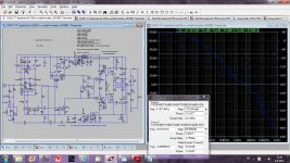
OK Manso, I am not JCX but here is my TT TMC VFB amp. Could you beat it with your CFB amp. I tried but can't go close to it even with the same PHM and GM. this is just thecnical challenge not listening perception.
BR Damir
Attachments
About 'words', this is, indeed, all you seems to do.yes I see "words" - not technical arguments
Just take any real *existing* VFA in your possession, and modify-it for CFA. You seem very experienced in poles etc. it should not cause you problems and you will get by yourself response to all your questions.
About 'words', this is, indeed, all you seems to do.
Just take any real *existing* VFA in your possession, and modify-it for CFA. You seem very experienced in poles etc. it should not cause you problems and you will get by yourself response to all your questions.
JCX is right about your non working file.
I already pointed that your so called "VFA" has a VAS
that work in class B , not to say C.
For the sake of the discussion i point what you did forget
when "calculating" your circuit :
You erroneously assumed that the input stage current sources
1mA or so current is entirely running through the input transistors
but thoses transistors emitters are at +-0.65V potentials respectively
for the PNP and NPN input transistors , as such there will be 0.65mA
current that will be drained by the 1K FB resistors that goes to the output ,
hence only 0.35mA will go through the input transistor , creating only
0.49V voltagge drop acrross the VAS base resistors....
Here your schematic so everyone can judge by himself.
Attachments
1nV/rtHz Ein power amp?
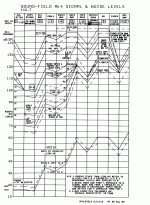
There are many factors in the noise of a large system and you have to consider where the important ones are if you not to have your horn tweeters hiss at you. The range around 4kHz is the important one which probably means attention to both your compression driver & horn tweeter paths.
May I suggest you do a levels & noise diagram on your complete system from player to horn(s)?
Attached pic is for the Mk4 Soundfield and is similar to what should be done on a big mixer. It shows overload levels & noise at each stage. It is for -10dB and -25dB on the fader as these were the most important positions.
You might want to do the chart for -6dB (worst case) and -20dB (typical use) on your Volume Control.
Doing this will immediately tell you what you need to improve.
A simpler example is described in NWAVguy's O2 headphone amp but the same principles hold.
In this (and your) case, it is vital to have as little gain as possible after the volume control. Anyone know of good 150W 8R voltage followers 🙂
You need to know the approximate gains (and any electronic EQ) in the 4 amps for your active system to do this stuff properly.
IMHO, juggling gains & levels systemwide will be more productive than attempting 1nV/rtHz Ein power amps. (BTW, don't forget that running too high a current in BJT LTP i/ps raises the current noise which is important with volume controls.)
_________________
Should point out that I know of only 2 properly implemented commercial P48V mike preamps with <1nV/rtHz measured Ein, the Earthworks & Millenia Media. (There is loadsa other stuff obviously measured by Marketing VPs)
Using the excellent THAT 1510 chip, a really good designer might get within 1dB of their potential 1nV/rtHz performance but only for something like a dedicated ribbon preamp. For real life P48V, 1.6nV/rtHz is the best possible and only if you're really good.
Alas, the important bits in the Earthworks preamp are fully encapsulated. I'm guessing from my & some other competent people's efforts at determining David Blackmer's design. The input devices are probably not LM384 which is now Unobtainium but it is unlikely the new uber OPAs will show any advantage over good ol' NE5532 in this application. Some of them have subtle & less well known disadvantages too.If I open up my Earthworks mic pre is that what I am going to see? Or is it a more modern version of that circuit with later discrete components?
Dave, IMHO you should revise your spec to eg 10nV/rtHz at the OUTPUT rather than specify an input spec.Dave Zan said:Around 1 nV/rt Hz looks achievable without serious compromise to other parameters and would be lower than practically any commercial product I know.
And I value simplicity too Partly because I have to build a whole set of them.
There are many factors in the noise of a large system and you have to consider where the important ones are if you not to have your horn tweeters hiss at you. The range around 4kHz is the important one which probably means attention to both your compression driver & horn tweeter paths.
May I suggest you do a levels & noise diagram on your complete system from player to horn(s)?
Attached pic is for the Mk4 Soundfield and is similar to what should be done on a big mixer. It shows overload levels & noise at each stage. It is for -10dB and -25dB on the fader as these were the most important positions.
You might want to do the chart for -6dB (worst case) and -20dB (typical use) on your Volume Control.
Doing this will immediately tell you what you need to improve.
A simpler example is described in NWAVguy's O2 headphone amp but the same principles hold.
In this (and your) case, it is vital to have as little gain as possible after the volume control. Anyone know of good 150W 8R voltage followers 🙂
You need to know the approximate gains (and any electronic EQ) in the 4 amps for your active system to do this stuff properly.
IMHO, juggling gains & levels systemwide will be more productive than attempting 1nV/rtHz Ein power amps. (BTW, don't forget that running too high a current in BJT LTP i/ps raises the current noise which is important with volume controls.)
This is only true of the popular evil 'diamond' IPS in many CFA designs. If you use a much simpler IPS eg like a symmetrical version of JLH Class A amp, it has less noise than a VFA with similar number of devices .. not that I'm championing CFAs, just pointing out a noise advantage.Bonsai said:Noise - CFA wont match VFA designs in general, but as I mentioned on a previous post, ultra low noise is not a requirement for a power amp
_________________
Should point out that I know of only 2 properly implemented commercial P48V mike preamps with <1nV/rtHz measured Ein, the Earthworks & Millenia Media. (There is loadsa other stuff obviously measured by Marketing VPs)
Using the excellent THAT 1510 chip, a really good designer might get within 1dB of their potential 1nV/rtHz performance but only for something like a dedicated ribbon preamp. For real life P48V, 1.6nV/rtHz is the best possible and only if you're really good.
Attachments
Last edited:
QUOTE Originally Posted by Kindhornman View Post
michaelkiwanuka,
Haven't we been down this road long ago. All the early Japanese solid state equipment measured almost no distortion with their test protocols and we all agree that the majority sounded terrible. I am not in any way saying to ignore the test equipment, that would be stupid, but the final test always seems to be do people like the sound when everything is finished. If it measures great but sounds terrible who is right the machine or the ears?
All this seems to be pure legend, far too often repeated.
Can you give the names of these early Japanese solid state equipment wich measured almost no distortion ?
It is quite puzzling that some guys of a younger generation hearing these early japanese amplifiers today found them very good.
At that time, circa 1970-75, numbers for minimal harmonic distorsions for these amps were about 0.03%. Due to slower output devices than those available today, better numbers were unobtainable because the amount of negative feedback was then quite limited. Today, the harmonic distorsions of the best designs which do not need to be extravagantly sophisticated approach 0.0003% 10 kHz., thanks to a high grasp of the feedback behaviour
If an amplifier measures good but sounds awful, it means that the measuring procedure was incomplete. There are no audible defaults which are not detectable by standard tests.:/QUOTE
Agreed!
michaelkiwanuka,
Haven't we been down this road long ago. All the early Japanese solid state equipment measured almost no distortion with their test protocols and we all agree that the majority sounded terrible. I am not in any way saying to ignore the test equipment, that would be stupid, but the final test always seems to be do people like the sound when everything is finished. If it measures great but sounds terrible who is right the machine or the ears?
All this seems to be pure legend, far too often repeated.
Can you give the names of these early Japanese solid state equipment wich measured almost no distortion ?
It is quite puzzling that some guys of a younger generation hearing these early japanese amplifiers today found them very good.
At that time, circa 1970-75, numbers for minimal harmonic distorsions for these amps were about 0.03%. Due to slower output devices than those available today, better numbers were unobtainable because the amount of negative feedback was then quite limited. Today, the harmonic distorsions of the best designs which do not need to be extravagantly sophisticated approach 0.0003% 10 kHz., thanks to a high grasp of the feedback behaviour
If an amplifier measures good but sounds awful, it means that the measuring procedure was incomplete. There are no audible defaults which are not detectable by standard tests.:/QUOTE
True.
Agreed!
Last edited:
Err.rrh! I can't remember exact details of the NAD3020 and there were differences between that and the 3020A but the QUAD 405 is current feedback.I remember when 30 years ago my friend bought budget priced system NAD3020/Tannoy Mercury M20. I was shocked because it sounded better than my own expensive system (Quad 34/405 + 15" Tannoy Berkeley MK2 factory made, not kit). It took me years to understand that it sounded better because of the current feedback power amp circuit, very similar to the circuit of old Revox amp that forum member Banat has. It remains mystery for me if the NAD circuit was chosen because of superior sound quality or was it purely economical decision.
IMHO, the differences in sound are due to the speakers .. I have this from the designers including Alex Garner who is their R&D boss.
Can you post the LTspice .ASC files & your models too please. 'Stripped down' is good for me cos my small brain might be able to unnerstan it.Tell you what, JCX, Ill post some sims results from stripped down version of a CFB amp. This amp is used on a daily basis.
For me, the most important aspect of the Self & Cordell books is that they present their 'real life' experience, measurements and the subtle caveats for their favourite VFB topologies.ivanlukic said:The consumers do not really have a chance to compare CFB and VFB because VFB dominates. If consumers were given a chance to compare, no doubt that many would choose CFB. And the reason that VFB dominate is because in industrial environment it is easier to mass produce VFB amps.
Every engineer is forced to be industry servant because every engineer needs salary. But when writing a book he can allow a luxury of being independent thinker!
This is far more useful and Unobtainium than the pontificating you find on this & other forums. If Self & Cordell write at length on CFB amps, it would be pure pontificating as they have little or no 'real life' experience with CFB amps. Maybe as useful as getting MikeK to write about VAS in amps. 🙂
So yus CFB fans are the ones to write a book about it.
Please make sure your details, sims & 'real life' measurements are up to Self & Cordell standards and don't forget to include 'real life' comparisons, measurements etc with 'equivalent' VFB amps.
Last edited:
- Home
- Amplifiers
- Solid State
- Audio Power Amplifier Design book- Douglas Self wants your opinions