Yep, there it is. ISSCC-1987, THAM-14.5 (pp. 176-177). I attended that conference but didn't see this presentation myself; I was in the "Grand Ballroom West" watching session 11.
Check out the amazing, for 1987, fabrication process
Check out the amazing, for 1987, fabrication process
The process has 600 MHz fT NPN transistors and 700 MHz fT PNP transistors, with beta*EarlyVoltage products of 10000 or more, and VCEOs higher than 36V. Low collector resistances are obtained by the use of buried layers and plugs.
Last edited:
@Chris Hornbeck, A perfectly high output impedance transconductance input stage, followed by lossy RIAA, followed by perfectly high input impedance second stage, has frequency response independent of stage gains. This isn't something easily done with the usual monolythic opamps, but is very interesting for discrete designs.
When I correctly understand, you are describing a CFA like the AD844.
@Hierfi made an interesting design with this opamp.
I started a thread on a linearized programmable transconductance amplifier (pTA) that uses an AD844, as per the link below. The feedback around the input network dramatically reduces the open loop distortion manifest by the input stage.
The pTA consists of a connected pair of OTA's to simplify balanced input/output functions, wanting to avoid the matching of numbers of precision resistors without resorting to INA's necessarily. It takes advantage of the formidable current mirroring (shown below on the right) and the CMRR already existing in AD844 devices, adding a linearization input network using an NE5532 dual VFA op-amp. Although this pTA cannot match the minimalist distortions or CMRR capabilities of the best INA's it does an excellent job IMO without using global feedback, producing a pair of differential...
- Hierfi
- Replies: 4
- Forum: Analog Line Level
This was later used in a MC phono stage that was constructed using an LT1115 in conjunction with a Denon 103R. As can be realized this can easily be implemented using an OPA1656 for MM cartridges as well.
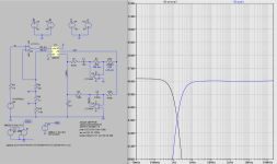
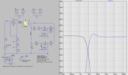
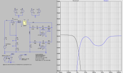
The linearized pTA feeds a current mode passive RIAA output network, that as a result doesn't suffer from the overload limitations of voltage driven passive RIAA networks. It uses dual feedback networks around this passive network, being fed from the unity gain buffer output of the AD844 being folded back on itself. The feedback contains a DC servo mechanism, that when set to about 1 Hz doesn't significantly affect the RIAA. Note the peaking that occurs when the frequency rolloff is increased to ~6.5Hz. Also that the network uses offset trimming on the LT1115 to set the initial zero for the servo.


The secondary feedback network targets the 500.5 Hz pole. The primary function was to support standard values of matched pairs of COG/NPO's or teflon capactitors to avoid the requirement of ratio-metric relationship. In other words the ratio-metric requirement is a function of resistance not capacitance. By creating approx. a 2:1 ratio-metric relationship of capacitances this also supports potentiometric fine tuning by R7 of the RIAA to about +/- 2dB. In other words using a 20k linear potentiometer with detent at 10K sets the flat response and whereupon 0 Ohms to 20kOhms the extremes.


Last edited:
As we are on the subject (sort of) although it's quite the departure in a sense.
There is a thread with a CFA buffer plus the rest of a phono stage design that I started.
RIAA accuracy within +/- 50mdB over manufacturing tolerances. C-120dBc 1kHz THD at 2v RMS out.
FET input, extremely low noise.
Plus or minus a few pages. The evolution took place in real time.
I don't want to derail this thread more than I have so I will end this diversion.
There is a thread with a CFA buffer plus the rest of a phono stage design that I started.
RIAA accuracy within +/- 50mdB over manufacturing tolerances. C-120dBc 1kHz THD at 2v RMS out.
FET input, extremely low noise.
Ultra high spec. opamp MC/MM phono, warp "elliptic" filter, line, headphone amps.
This is a project that has been on Audio Karma for about a year and has had a number of revisions, additions and upgrades.
There are about 150 of the units in various versions out in the field and it was repeatedly suggested by builders that a thread be opened in DIYaudio- so despite some reluctance here it is.
As the title suggests, it is opamp based, and is hardly unique, but it has some unusual features and has stellar specs and is pretty easy to build.
Some features:
1. Optional parallel input...
- wynpalmer2
- Replies: 334
- Forum: Analogue Source
I don't want to derail this thread more than I have so I will end this diversion.
@EdGr,
What can a discrete design improve to an integrated design using the same elements ? Even companies like Mark Levinson that went on a long time using discrete designs when others switched, are now also using opamps in preamps and main amps.
Hans
I'm not Ed and I don't know what you mean by "the same elements", but discrete designs can for example use current as the signal quantity, use higher-order frequency compensation (or use plain first-order frequency compensation that is tailored to the application), or work in class A instead of AB. In fact, the same holds for an IC design, but not for an op-amp design (discrete or IC op-amp).
I have hoped this topic had already been a dead horse.
Below THD vs. frequency plot with 6 different opamps in a linear gain stage with 30.4 dB gain, non-inverting circuit.
LM6171, ADA4898, LT1028, AD797, OPA637, AD829. Vout = 1.68V.
Of those, lowest OLG have LM6171 (90dB), ADA4898 (100dB) and AD829 (100dB)

Below THD vs. frequency plot with 6 different opamps in a linear gain stage with 30.4 dB gain, non-inverting circuit.
LM6171, ADA4898, LT1028, AD797, OPA637, AD829. Vout = 1.68V.
Of those, lowest OLG have LM6171 (90dB), ADA4898 (100dB) and AD829 (100dB)
Thx Marcel,
it must be obvious what is meant with the same (active and passive) elements, isn’t it.
But for audio applications, without going into further detail, the only thing that really counts IMO is whether amplifiers constructed around discrete circuitry instead of opamps, of course only at positions where thst’s possible, have a sound that is perceived to be superior.
If not, I don’t see a good reason to abandon opamps.
Hans
So it’s a dead horse like you said.And then we go to ask for a DBT, to avoid biased impressions.
Hans
From the other thread about op-amps going non-linear, I thought that you would be happy that an op-amp with moderate open-loop gain and more degeneration can compete in the THD wars.I have hoped this topic had already been a dead horse.
Ed
@Hans Polak It is. Still I would like to see a proof that low OLG is good. A proof supported by measurements of some kind, not by stories. Otherwise, the thread does not make much sense, at least to me.
The flaw with that argument is that modern opamps can have all of this and have ~140dB open-loop gain and be stable at noise-gain=1, so they will win hands-down. And they are small enough to pick up much less interference than a discrete design - once distortion is down at ppm levels, noise pickup can easily dominate the SINAD figures...design an amplifier with good open-loop linearity, bandwidth, and PSRR, and apply moderate feedback
@PMA - I have only simulations of differential pairs and output stages. I believe they are accurate as much as Ebers-Moll is accurate.
@Mark Tillotson - This topic got started because of observed non-linear behavior in super high-gain op-amps. The non-linear behavior is a result of tiny voltages leading to overload.
Ed
@Mark Tillotson - This topic got started because of observed non-linear behavior in super high-gain op-amps. The non-linear behavior is a result of tiny voltages leading to overload.
Ed
DBT seems more often to result in biased conclusions than negating impressions, biased or otherwise.And then we go to ask for a DBT, to avoid biased impressions.
@PMA - I have only simulations of differential pairs and output stages. I believe they are accurate as much as Ebers-Moll is accurate.
@Mark Tillotson - This topic got started because of observed non-linear behavior in super high-gain op-amps. The non-linear behavior is a result of tiny voltages leading to overload.
Ed
So there must be a proof when measuring or simulating a complete circuit as a black box. A proof of worse linearity. Not only an analysis of a separated part of the complete circuit.
https://linearaudio.net/sites/linearaudio.net/files/volume1bp.pdf
Why? Sighted tests are better?DBT seems more often to result in biased conclusions than negating impressions, biased or otherwise.
@PMA - I have seen that paper.
I have been simulating the building blocks so that I can understand the causes of distortion. The assumption is that the amplifier can be designed so that one block dominates distortion. I believe that this is reasonable as long as one is not aiming for super-high gain.
Let's drop discussions of DBT.
Ed
Simple nonlinear distortion isn't the only thing that can affect SQ. Of course there is phase distortion, sometimes made worse by poor servo design. There is also correlated noise/noise-like-distortion that is not so easily seen on a typical audio spectral FFT plot.
Could be the more loop gain, then the more that passive feedback components and layout can add colorations that don't show up as narrow spectral lines confined to one FFT bin.
IOW, if two devices sound different there may be cause to go looking for a physical mechanism before jumping to conclusions that listeners are imagining things.
Moreover, DBT is rarely conducted properly. Down around the thresholds it gets tricky not to be find bias in the form of false negatives. IEC has a very good standard for proper blind testing but its complicated, time consuming, and costly to do it well. In addition, ABX is known to biased toward false negative outcomes in untrained test subjects. There are better protocols and or ways to properly train test subjects.
- Home
- Design & Build
- Electronic Design
- Audio Opamps