Are there any more listening impressions around? Maybe compared to single tube SET?
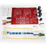
Looks like a very nice kit.
Looks like a very nice kit.
Are there any more listening impressions around? Maybe compared to single tube SET?
Looks like a very nice kit.
I ended up trading it for a Canary Audio tube amp and regretted from day 1. It was a very nice amplifier!
Very nice build. The Mundorf caps are part of the kit aren't they as are the JJ EL84s?
How about the NOS Telefunkens?
Thanks for all the pictures and information. Think I may pull the trigger on one of these.
How about the NOS Telefunkens?
Thanks for all the pictures and information. Think I may pull the trigger on one of these.
Yes, the Mundorf are part of the kit and they use very high end parts and may use better resistors than what they had back then. I may have acquired the Telefunkens somewhere else though...Very nice build. The Mundorf caps are part of the kit aren't they as are the JJ EL84s?
How about the NOS Telefunkens?
Thanks for all the pictures and information. Think I may pull the trigger on one of these.
Don't think you will regret pulling the trigger.
I bought and populated (as at the origin) a clone of L1.
having several pairs of opt at home, I did not buy the audionote opt.
so I'm going to assemble it on a bread board and see what it gives.
I am amazed that no one else has reacted on this thread for all this time, especially with the number of clones available on the planet.
having several pairs of opt at home, I did not buy the audionote opt.
so I'm going to assemble it on a bread board and see what it gives.
I am amazed that no one else has reacted on this thread for all this time, especially with the number of clones available on the planet.
I bought and populated (as at the origin) a clone of L1.
having several pairs of opt at home, I did not buy the audionote opt.
so I'm going to assemble it on a bread board and see what it gives.
I am amazed that no one else has reacted on this thread for all this time, especially with the number of clones available on the planet.
I've been interested in this clone design too. Would like to retrofit this AN design into my existing ChiFi enclosure and use same transformers- but need to research impedances and wattage ratings first. Already started designing new PCB to fit existing enclosure for fun- be a little smaller board, but power supply will be moved off saving space.
Jim
Attachments
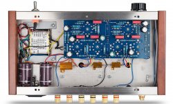

I chose a different way.
I bought the L1 pcb clone and populated it with good components.
I will try to respect the original kit as soon as possible because Audionote is far from being a beginner in this area.
I also do not like Chinese opt, it can be good but then you have to put the price, I prefer to use ops that I know, in this case Supersonic.
ditto for power supply, they planned wide in terms of power, I also chose this way.
ditto for the tubes ,i have many lots of el84 , 7189 and ecf80 .
you have the chance to be in the usa and to be able to buy Hammond and Edcor for a reasonable price as well as good quality 7189 or EL84, it would be a shame to deprive yourself.
when it's 100% Chinese, I do with it and I adapt, but then it's a shame not to do something nice and beautiful.
We can move forward together if you want, it will be with pleasure.
I am in the integration in the case
I built a L1 clone for a friend of mine - it sounds very good. Having everything
on one (large) PCB has it's advantages, but I think what Jim (oemcar) is doing
makes it much easier in terms of enclosure design.
Look forward to the new board.
on one (large) PCB has it's advantages, but I think what Jim (oemcar) is doing
makes it much easier in terms of enclosure design.
Look forward to the new board.
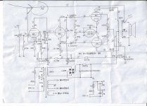
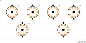
The 6BL8 concertina uses 33k resistors in the cathode and plate (correct, same value).
The 6F2 concertina uses 27k in the plate and 30k in the cathode.
The signals from that concertina are slightly unbalanced.
That will cause the 6P1 push pull pair to have a little 2nd harmonic distortion, but the global negative feed back will cancel most of that.
It would be interesting to do a listening comparison, to both the unbalanced and balanced concertina versions.
A single resistor change allows that.
If you have the 33k 33k amp, change one of those to 30k.
If you have the 30k 27k amp, change one of those to match (two 30k, or two 27k).
Have fun listening!
Last edited:
I chose a different way.
when it's 100% Chinese, I do with it and I adapt, but then it's a shame not to do something nice and beautiful.
We can move forward together if you want, it will be with pleasure.
I am in the integration in the case
I agree with your overall design logic-
But my primary focus as a hobbyist is to work on an ascending price structure- as such, transformers tend to be costly..
So lets upgrade cheaper parts first before taking the next monetary step
Jim

@6A3sUMMER
_"If you have the 33k 33k amp, change one of those to 30k.
Have fun listening!"
I have 33k+33k
I will try in this configuration and change one of the two to see
@ oemcar
with this objective, I am 100% ok with this approach
@ RE 604 "E80CF from Valvo ."
E80CF,well done 🙂
i didn't think about it(like E80F for EF86) .
however you don't say anything about the amp itself, I mean, how it sounds, if you like it etc etc
huggygood,
I think we did talk about that.
I have talked about the balanced / unbalanced concertina more than once on various threads in this diyAudio forum.
I think we did talk about that.
I have talked about the balanced / unbalanced concertina more than once on various threads in this diyAudio forum.
indeed, I could see during my research and through different diagrams that sometimes it was balanced, sometimes not and sometimes there was a balancing pot, which suggests that others are posed the question before us 😀
Unless the tube draws grid current,
Unless the tube has filament to cathode leakage,
Unless the tube has way too much filament to cathode capacitance,
Then, matched resistors in the concertina cathode and plate, plus matched resistors in the next stages grid resistors, and if the next stage grids do not draw grid current, there will be perfect balance of the amplitudes of the two phases of signal.
Why is it that some wives tales always want to go contradictory to math and physics?
It has the merit of being clear as always ... 🙂
as we are here to discuss interesting things, I would like to come back to the balancing pot in the bias cathode circuit like on the HK A500 for example.
I adopted this principle on almost all of my amplifiers using the bias cathode with great success, in particular on my A300 and my XAM.
I would like to have the opinion of other people on this point and why not, on the L1
the child uttered his first cries and it is remarkable !!
yet assembled in bulk in a box "to see what it gives" it is perfectly silent and is really very good.
I think it can be wired in UL, I will try after
yet assembled in bulk in a box "to see what it gives" it is perfectly silent and is really very good.
I think it can be wired in UL, I will try after
Last edited:
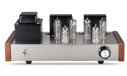
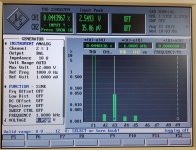
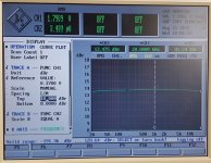
Hello ,
I build this clone last year and measured it . I use TFK EL84 with round plates and E80CF from Valvo .
Kind regards , Alexander .
Wow!
Those graphs are impressive! What wattage would you estimate these measurements taken at? Looks like 5W load resistors in place of speakers? does this have affect on graphs?
Jim
Last edited:
huggygood,
I do not have a schematic of an HK500, so I can not comment on its bias circuitry.
I do not have a schematic of the XAM either, so I can not comment on its bias circuitry.
I did own an HK A300.
The output stage bias circuitry makes me think of the following analogy:
4 persons were honored to carry a small Casket of their good friend who passed away.
3 were young and strong. One, on the Left front of the Casket was 95 years old, and very frail.
The 3 strong ones had to make up for the 1 weak one.
None of the crowd noticed that the Casket almost tipped over.
3 strong 6V6s, and 1 weak old 6V6 were biased with a common cathode resistor, consisting of two 12AX7s filaments in series.
The relatively small output transformer that had one strong 6V6 and one weak 6V6 was near saturation even before any bass signals were applied, due to the two un-balanced plate currents.
There also was no easy way to notice if one 6V6 was very weak, or if instead all 4 6V6s were each a little weak.
Changing to individual self bias resistors changes all of that, but does work.
24V / 37.5mA per 6V6 = 640 Ohms for each 6V6 cathode resistor (less watts / resistor).
And you have to find room for 4 bypass capacitors (modern ones are smaller now for the same voltage and capacitance ratings than they were when the A300 was produced).
But now you also have to provide 12.6 VDC @ 300mA for the two 12AX7 filaments
(or 25.2 VDC @ 150mA).
Individual Adjustable Fixed Bias also works, as long as you can adjust each individual tube current. But you have to adjust by going back and forth to match all 4, unless the B+ is Regulated.
Using a combination of Adjustable Fixed Bias, plus some self bias also works.
But the resistors for the self bias have lower resistance, since most of the bias voltage is from the adjustable fixed bias circuit, and not from the self bias resistors.
The disadvantage is that the tube does not control its own current as well as it would when all the bias voltage comes from only self bias circuitry.
It is a function of the cathode impedance versus the self bias resistance.
UL operation requires either a UL transformer, or more complex circuitry.
And that is just another part of the continuing story of tradeoffs.
- Home
- Amplifiers
- Tubes / Valves
- Audio Note Kits L1 Build...