Dear Oracle,
I have an Audio Innovations set, 1x S200 Preamplifier MM model, and 2x 200 MK2 power amps.
I want to install the MC section and upgrade the preamplifier.
I need the schematic for the preamp, does anyone out there have one or know where I can get one?
I already have the power amp schematic.
Thank you
Hi Euro21,
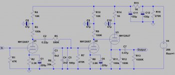
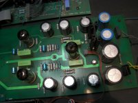
Thank you for the schematic but it seems that it does not agree with what I have on the bench. I notice that my amp has 4x 0.47uF caps and your schematic only 1? I have attached a picture of my amp for clarity. If you have any other leads or schematics that would be great.
best
Steve
Thank you for the schematic but it seems that it does not agree with what I have on the bench. I notice that my amp has 4x 0.47uF caps and your schematic only 1? I have attached a picture of my amp for clarity. If you have any other leads or schematics that would be great.
best
Steve
Attachments
It was more than a decade ago ... but now I use 220nF as "first" capacitors.
There I also wrote some information:
Audio Innovations Series 200 Phono Stage
The "MC" stage is unusable.
I tried it, but even with low noise 5751 tube it's only a hiss producer.
I use E.A.R. Paravicini MC3 transformer for my Supex 900 pickup.
There I also wrote some information:
Audio Innovations Series 200 Phono Stage
The "MC" stage is unusable.
I tried it, but even with low noise 5751 tube it's only a hiss producer.
I use E.A.R. Paravicini MC3 transformer for my Supex 900 pickup.
Last edited:
Thanks again Euro21.
I have read the thread you directed me to....very interesting list of mods. I want to try a few, so do you have any details? Like;
AI200 tweaked:
- HEXFRED diodes in both power supply (high voltage, heater);
- CRC snubbers in both power supply; Have you values and positions?
- 5 H choke in HV supply (C-L-C); Have you values and positions?
- BlackGate supply capacitors; Which ones are these?
- NOS Sylvania (3 mica) 5751 tubes in first positions;
- NOS Tungsram ECC82 tube;
- LED (green) bias in first and second tubes cathodes; How does one do this?
- AuriCap coupling capacitors (0.22, 0.47);
- direct phono input, Cardas RCA, silver coax; How?
- Vishay S102K phono input resistors;
It was the early "Quasimodo", like this:CRC snubbers in both power supply
TJERET FILE: Snubberized power supply (Quasimodo)
There is a resistor between first and second HV capacitor. Change it to choke with appropriate DCR (if I remember correctly it was larger than power transformer).5 H choke in HV supply (C-L-C)
I tried to change six 47uF 400V capacitors to BG VK ones (it was a pricey game), but later remove its, and change all to Rubicons.BlackGate supply capacitors
I killed R//C in cathodes, and exchange its to old 5mm green LEDs.LED (green) bias in first and second tubes cathodes
I inserted Cardas RCA sockets in the rear side "MC" holes as direct phono input.direct phono input
There is a (input) ribbon cable in the front of the main panel.
I killed it, and connected directly to pins the input shielded cable from RCA.
Euro21,
That is great....
Have you a diagram for your LED mod, I do not understand how this works or where it fits in the schematic? Do you mean; replace the 220u cap // 3k3 R and 220u//3k6 R in the schematic with green LEDs? If so, do you not need a resistor to limit the LED current?
That is great....
Have you a diagram for your LED mod, I do not understand how this works or where it fits in the schematic? Do you mean; replace the 220u cap // 3k3 R and 220u//3k6 R in the schematic with green LEDs? If so, do you not need a resistor to limit the LED current?
Guy Sergeant, one of the Audio Innovations founders, posts regularly on the Pink Fish Media audio forum (audio | pink fish media) under the moniker Puresound. He is very forthcoming with advice and information on all of the AI products.
Alex
Alex
Thanks Alex,
I have been in touch with Guy and he sent me the schematics.
Now the fun can commence.
I have been in touch with Guy and he sent me the schematics.
Now the fun can commence.
- Home
- Amplifiers
- Tubes / Valves
- Audio Innovations S200 Schematic request