For some reason, I never saw the 'more pics' post. Probably because I use the 'go to last post' option. No need for more photos.
Remove the drivers and check/compare the amplitude on the collector of Q7 and 11. Also confirm that they're swinging to their corresponding rails.
Remove the drivers and check/compare the amplitude on the collector of Q7 and 11. Also confirm that they're swinging to their corresponding rails.
amplitude is still not matching, please see below:
positive rail/drive
neg rail/drive
positive rail/drive
An externally hosted image should be here but it was not working when we last tested it.
neg rail/drive
An externally hosted image should be here but it was not working when we last tested it.
Just to confirm, the waveforms on the bases and emitters of Q7 and 11 are of the same amplitude. Is that correct?
And the resistors R22, 29, 13 and 27 are all within tolerance. Is that correct?
And the resistors R22, 29, 13 and 27 are all within tolerance. Is that correct?
Yes the waveforms are of equal amplitudes. The 470 ohm above the transistors are within tolerance, will confirm the rest tomorrow.
Are you posting images as described below?
To upload photos click the following:
Go Advanced
Manage Attachments
Browse
Upload
Repeat as necessary
Preview post to see how the post will look.
Click Submit Reply to send it to the forum.
To upload photos click the following:
Go Advanced
Manage Attachments
Browse
Upload
Repeat as necessary
Preview post to see how the post will look.
Click Submit Reply to send it to the forum.
Please upload all images that way. All of the other images were lost.
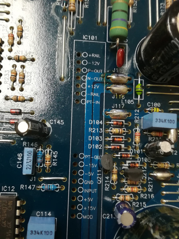
The PT-in will be at the negative rail.
PT-out will be near 0v.
MOD will be a square wave swinging ±5v.
The PT-in will be at the negative rail.
PT-out will be near 0v.
MOD will be a square wave swinging ±5v.
- Home
- General Interest
- Car Audio
- Audio Gods AG 7000.1D