Background:
I'm pondering a design which uses TV sweep tubes as the output devices, based on an article which revisits Crowhurst's twin coupled amplifier.
In the article, the author mentions that the power dissipation of a sweep tube can be safely increased by ~40% in an audio amplifier application. A reference to the RCA Receiving Tube Manual is cited, and sure enough, there are examples there.
In this design, the anode voltage is pretty much at the design max rating of 400 V, and the screen grid voltage is at 320 V (design max is listed as 300 V). Fixed bias is used in this design.
The Question:
I'm at a point where I'm attempting to draw load lines, and I'd like to understand what's happening. The problem I think I have is that the data sheet only has cathode current and anode voltages up to a screen grid voltage of 150 V. How do I go about estimating the effect on power and grid voltage swing where the screen grid voltage is almost literally off the chart? Does it even matter?
weinstro said:
In the article, the author mentions that the power dissipation of a sweep tube can be safely increased by ~40% in an audio amplifier application. A reference to the RCA Receiving Tube Manual is cited, and sure enough, there are examples there.
That looks about right. TV HD amps are a good deal tougher than audio finals. Some better than others. (For 6BQ6GTBs, the Sylvania black plates can take considerably more power without red plating than can the RCA grey plates.) YMMV
In this design, the anode voltage is pretty much at the design max rating of 400 V, and the screen grid voltage is at 320 V (design max is listed as 300 V). Fixed bias is used in this design.
Seems kind of high for a HD, unless it's that rebottled 807: the 6BG6
I'm at a point where I'm attempting to draw load lines, and I'd like to understand what's happening. The problem I think I have is that the data sheet only has cathode current and anode voltages up to a screen grid voltage of 150 V. How do I go about estimating the effect on power and grid voltage swing where the screen grid voltage is almost literally off the chart? Does it even matter?
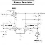
Say what! If the characteristic calls for a Vsgsg= 150V, then best to supply that by means of an active screen regulator. That'll stabilize the screen voltage, and present the screen with a very low AC impedance to ground, both very important for good linearity. For a project I did with 6BQ6GTBs, I included this screen regulator.
Attachments
That looks about right.
OK - good to validate.
Seems kind of high for a HD, unless it's that rebottled 807: the 6BG6.
Compactron, actually. 6LU8.
Say what! If the characteristic calls for a Vsgsg= 150V, then best to supply that by means of an active screen regulator. That'll stabilize the screen voltage, and present the screen with a very low AC impedance to ground, both very important for good linearity. For a project I did with 6BQ6GTBs, I included this screen regulator.
Yup, seems odd. "Average Characteristics" are Plate Voltage = 135 V; Screen Voltage = 120 V. GE only provides for screen voltage <= 150 V.
"Design-Maximum Values" are Plate Voltage = 400 V; Screen Voltage = 300 V.
The design I'm trying to understand operates the tube at Plate = 390 V and Screen = 320 V. Both are fed from a regulated supply, but not like the one you posted.
Thoughts on completing load lines analysis?
Re: Re: Audio applications of sweep tubes and ratings
The GE characteristic does look very odd. I'd guess that they were probably trying to tailor it to TV sets that ran directly off the AC mains without a power xfmr. About the only way you could analyse that is to draw up new characteristics for the higher screen voltages.
weinstro said:"Design-Maximum Values" are Plate Voltage = 400 V; Screen Voltage = 300 V.
The design I'm trying to understand operates the tube at Plate = 390 V and Screen = 320 V. Both are fed from a regulated supply, but not like the one you posted.
Thoughts on completing load lines analysis?
The GE characteristic does look very odd. I'd guess that they were probably trying to tailor it to TV sets that ran directly off the AC mains without a power xfmr. About the only way you could analyse that is to draw up new characteristics for the higher screen voltages.
I used some PL509s, and PL519s for PP amplifier. I can tell You, that not necessary to go over 200V, for 120W from one pair of PL509. In normal operation the PL509 gives nice 100W with 150V screen, and 450V anode.
I used them as triode too. With 300V HT it can gives some 30-35W.
Sajti
I used them as triode too. With 300V HT it can gives some 30-35W.
Sajti
The Australian company Esoteric Audio Research used PL509 and PL519 in their EAR-509/EAR-519 that came also in kit form, I guess.
Kevin O'connor told me once... You will learn more with a soldering iron in your hand then a computer mouse. Build it, light it up, measure what you want to learn of it. When using tubes for purposes other than intended, you'll be the guy letting everyone else know what the manufacturers didn't. I built an amp with 6LU8's. Horizontal tubes typically have low screen voltage ratings. I built a sort of split supply with a 400V and 200V
output. 400 on the plates, 200 on the screens. Get in there!
output. 400 on the plates, 200 on the screens. Get in there!
Well.... doubling the screen voltage will more-or-less double the plate current for a given grid voltage/plate voltage point.
So you could get a rough approximation by just doubling the current numbers on the plate curves.
The problem is, I think the published plate curves won't have enough resolution to be very useful. At that screen voltage you'd have to be running -20V or more grid bias, which would put you at the very bottom of the chart...
So the bottom line is that you'll probably have to try just it. Make sure you measure & calculate the screen dissipation, I'd be a little worried about that.
Pete
It's been posted before but this a good deal on 6BG6GA's worth considering:
http://www.vacuumtubes.com/6BG6.html
I've rigged a pair in stead of 6L6GC's on a SET amp. I've ordered another six pairs.
http://www.vacuumtubes.com/6BG6.html
I've rigged a pair in stead of 6L6GC's on a SET amp. I've ordered another six pairs.
- Status
- Not open for further replies.
- Home
- Amplifiers
- Tubes / Valves
- Audio applications of sweep tubes and ratings