
I have one of those. Its called an isolator. Two built-in probes. Bandwidth is limited though. It optically isolated, good for maybe up to 3kV floating. Don't recall the exact spec at the moment.A few years later, they actually did it.
Last edited:
For HF noise, you just need to join the chassis. This keeps HF common mode noise to a minimum. This is a different mechanism to the ground loop discussed earlier.Bonsai, The chassis are not close to eachother, the PC is at least 2 metres away from the amplifier. There is no real option to connect all chassis together, since I have a lot of measuring equipment (signal generators, AC volt meters, wattmeters, etc.).
Note: The amplifier (KT150 PP) itself is very quiet. I check for “noise” and “hum” by connecting the amplifier output (from a dummy load) directly to a 50 Watt AKAI amplifier (line input). Of course there is a little noise with this extreme amount of amplification, but it’s very limited and without hum.
A HBR, if implemented as shown in post #8 has no effect in safety and is a widely used technique in commercial equipment.Get rif of that 10 Ohm! Not a single commercial unit uses this because it would never get through any safety certification. If you need it it means your grounding scheme is wrong.
One of the issues with isolation barriers like this is you can have very high HF common mode voltage across the barrier that couple capacitively into the input electronics side. So, although these techniques provide a great way to isolate high LF voltages and/or DC, you have to be aware of capacitive coupling. On my QA401, I connect the housing to the laptop (battery powered) USB shroud at the laptop, and then from the QA401 housing to the amplifier housing and then the amplifier housing to the load housing. The wide and noise floor is very low.Ah, an instrumentation issue, supposedly my major as an EE. How Tektronix screamed and cried when I tried to float one of their battery powered scopes - which would illuminate all these warnings about how it MUST be grounded on screen upon power up. The corporate powers wouldnt ultimately let me us an RS232 isolating device to float that scope. What's with the battery, then? To go dead and sell you a new one? My Fluke 123 doesnt seem to care, neither does their DMMs. The 123 even has an isolated RS232 cable.
We had the same issue doing bench measurement of power converter noise and dynamic response. All the bench stuff with its ground, the DUT with its ground. We ended up using diff probes, which are not within the budget of most DIYers. Some Yokogawa scopes had floating inputs, which we tried also.
One time Tektronix had a "what product would you like" meeting with us. I told them give me a probe with a fiber optic cable to the scope. They looked at me like I had 3 heads. "Why would you want that?". A few years later, they actually did it. I was gone by then, so never got to use one. Part of the tech in that probe was they send a laser beam down a fiber optic cable, converted to DC, to power the electronics in the probe tip.
It is to wonder how the USB isolator gets the power across isolated, to the DAC / ADC. You may want to examine that, in the particular device chosen. I'd expect the device on the isolated side to have its own power source, which sounds like a float to me, for Ground, DC and RF. Battery powered sound card.
I'd like to see that in the schematic of a commercial item.A HBR, if implemented as shown in post #8 has no effect in safety and is a widely used technique in commercial equipment.
Try this if an isolating transformer is available.
Use the isolation transformer to power your p.c.
Use another wall socket(directly ,not isolating)to power your amplifier or whatever you want to test.
If you haven't a success try the opposite.
Use the isolation transformer to power your p.c.
Use another wall socket(directly ,not isolating)to power your amplifier or whatever you want to test.
If you haven't a success try the opposite.
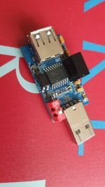
I use a USB isolator for circumvent the problem. Some ADUMxxxx.
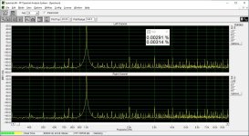
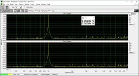
Here's an example of what such an isolator can do. This is a "loopback" between just a DAC and an ADC, both connected via USB to the same computer, with and without the isolator. (The DC power in this case is isolated by using a separate supply for the downstream side of isolator. Some commercial devices use isolated DC regulators, maybe based on SN6505's or similar. Batteries work, too.)
Prior to trying the isolator, I tried using a second computer for the ADC side. It was plugged into a different outlet on a different AC mains circuit. The spectral plot was just as bad, just different in composition. Using a laptop running on battery for the ADC side gave essentially the same result as using the isolator. Using an isolator is way more convenient, at least for me. E1DA sells an isolated version of their Cosmos ADC to make it even more convenient. Also, different DACs gave similar results.
Side soapbox comment: The original Cosmos ADC has a CMRR at its input of about 60 dB or so. (I measured, as did some others.) 60 dB is a lot more than most home audio gear in an actual listening system provides. See what you get with 60 dB? Keep in mind that the level of crud does not go down much with the level of the desired signal, so in real music playing applications those products might only be 60 dB below the average music level. And, that's with ~60 dB of CMRR on the receive end. How much CMRR does an unbalanced preamp or amp normally provide?
ADUM3160. There are higher speed devices, too. Here is my DAC without/with isolator.I use a USB isolator for circumvent the problem. Some ADUMxxxx.
Attachments
The issue I'm running into is that the pc's USB connector is internally connected to the pc's chassis (and thereby grounded). So by connecting the USB cable to the pc the 10 Ohm resistor in the amplifier is shorted and there is no longer a separation between the audio ground and the chassis ground.
Is that pc connected with an IEC cable to a wall socket with PE? And PE to be verified & actually connected at the end point? Just to exclude things.
These are nice riddles to solve IMHO but make sure to use the right terms for PE and (audio) GND for correct interpretation. Often they turn out to be relatively simple issues. Of course always afterwards when things have been solved 😉
Last edited:
Use balanced/diff input if your soundcatd has one.
Lift the chassis GND for the measurements (assuming you know what you are doing).
Lift the chassis GND for the measurements (assuming you know what you are doing).
JP: Both PC and amplifier (and lots of other measuring equipment) is grounded properly. PE is verified.
Mbrenna: How do I connect a BNC-probe to a balanced input?
Mbrenna: How do I connect a BNC-probe to a balanced input?
OK when PE is verified to be connected and measured to be working OK the USB plug shorts that 10 Ohm indeed. This situation very likely is best solved with galvanic separation. Maybe you could think of a WiiM Ultra or the like for optimal audio experience. Otherwise you will need an mains isolation transformer (won't solve it as it separates N from PE but of course leaves PE intact...), USB isolators, questionable PE choices etc. and the question is if it is worth all the hassle and the new drawbacks like jitter that possibly will be introduced. PC audio, more issues than fun.
Ho wait JP! "The external soundcard is connected to a pc with a standard USB cable". So nothing stops you from using 1:1 output transformers at the outputs of that external USB sound card (or way better: internally) and having galvanic separation at the analog side of things the most simple way. Except cost maybe. If you like you can try a pair for free like the dutch like a lot 🙂
Ho wait JP! "The external soundcard is connected to a pc with a standard USB cable". So nothing stops you from using 1:1 output transformers at the outputs of that external USB sound card (or way better: internally) and having galvanic separation at the analog side of things the most simple way. Except cost maybe. If you like you can try a pair for free like the dutch like a lot 🙂
Last edited:
Hi JP, I’m probably as Dutch as I can be…
I will try tomorrow what happens if I use the TRS for a balanced setup. I’m using two Steinberg UR242’s for audio input. They have 6.3 mm TRS inputs, so I may have some options there.
I also have a stereo RCA isolator, using small transformers. I haven’t used this for input, because of the transformers that may affect measurements. On the other hand I didn’t experience a difference listening with this isolator. It’s actually quite good.
Where is the BNC? On the amplifier or on the soundcard?How do I connect a BNC-probe to a balanced input?
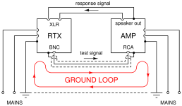
I guess I should have said differential input to make my point. You'd connect POS to the audio output of your amp, and NEG to the audio GND of the amp. There was an RTX6001 tutorial a while back here on diyAudio, which explained the grounding issue and the benefit of using a diff/balanced input on the soundcard. However, I believe the tutorial went dodo when they upgraded the software/system. I attached a drawing I made back then.
If your soundcard does not have a differential/balanced input, I'd simply lift the chassis ground during the measurements. The amp is on your workbench, and you know the ground is lifted, so you simply keep your fingers off. Put the ground back after the measurements, and before fingers or other vulnerable things get close to the amp.
Attachments
Problem solved for now using only TR from the 6.3 mm TRS connectors, Tip = hot, Ring = audio ground, Shield not connected. I made a short adapter cable to BNC. Cheapest solution too.
Both my Steinberg soundcards can handle this well and measurements are not affected by doing so (not in RMS voltage, not in the distortion measured).
Both my Steinberg soundcards can handle this well and measurements are not affected by doing so (not in RMS voltage, not in the distortion measured).
OK, that’s a good read. My adapter cable is very short and for now is without shielding. So far so good!
- Home
- Design & Build
- Equipment & Tools
- Audio and Chassis Grounding