
Hi,
did any one simulate it, could find any problams?
looks to be a very simple amp. my simulation is not working fine.
best regards,
Williams
did any one simulate it, could find any problams?
looks to be a very simple amp. my simulation is not working fine.
best regards,
Williams
Hi,
i have an Audioanalyse power amp with two monoblocs and need the schematic, can you provide any information. I think it has 100w per chennel classA, it has 8 transistors at final stage each channel.
The power supply and driver stage are in a big box, the final push pull stage has two umbilical cables with a big heatsink heads.
Any thoughts?
Thanks
yes, although i woudn t waste negative feedback to correct
a fuse nonlinarity...a relay would be a far better solution, moreover as
this is supposedly an audiophile oriented item...
It was made such a way to prevent damage of an input transistor when output one is blown.
It was made such a way to prevent damage of an input transistor when output one is blown.
to protect a 1 $ (at most) input transistor in case of blowing?..
and since the output is blown, no need of input transistors to
eventually correct the hard offset....
anyway, in such case, what is to be protected is the speakers,
and this hasardous nfb path has nothing to do with this purpose,
it s just some wicked cost killings..
The A9 does 60W in Class AB, 50W brochure spec.(Biggy A90 goes 120W, 50 in full Class A)
90W of heat on 160VA toroids in the A9 is pushing it, even if biased only to 25W continuous.
Schematic of the B90/P90 power amp section, 10W Class A and 100 in AB=>
Thanks, i have one of these as main amp. Think a B90mk2. Still works like a charm after all these years. Only changed the LS switch long ago, nothing else. Reliable... 🙂
to protect a 1 $ (at most) input transistor in case of blowing?..
$1 in parts costs much more in labor of a repairman.
I don't understand the concern about including the output fuse in the NFB loop. PS Audio did it with the 200c / 200cx as well. If the amp is fairly linear open loop, then that's exactly where it should be when operated with a blown output fuse. I don't see how opening the feedback loop is going to force the amp into some sort of runaway situation unless it's pretty non-linear OL and its gain is very much controlled by NFB.
But may be my assumption was wrong, and they included a fuse in a feedback path to minimize distortions caused by it on low frequencies, when temperature of it's filament follows the signal. As you know, resistance of a filament depends on it's temperature causing non-linearities.
Wavebourn,
that`s why my mother-in-law does not recommend fusible elements in the feedback path.
that`s why my mother-in-law does not recommend fusible elements in the feedback path.
Wavebourn,
that`s why my mother-in-law does not recommend fusible elements in the feedback path.
Hi Lumba;
when finally you convince her to register on our forum? I'm tired to wait... 😕
Taking up the topic ...
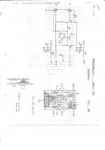
A friend has the A9 and I was looking for general information, the fuse holders having deteriorated, due to the deterioration of the plastic cover.
I found this post and ... also an Italian magazine where the couple C900 and A9 was reviewed.
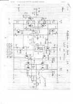
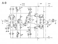
I agree with the scheme that engineer Montanucci commented on the basis of the test conducted and some of his statements summarized below:
"The circuit configuration of the A9 is classic and complies with the most commonly accepted criteria among the most popular audio designers, based on the absence of electronic current limiters, on the mirror symmetry from input to output and on the adoption of a moderate feedback.
After a mild preliminary filtering (1) at about 150 Khz, the signal is applied to a mirror pair of differentials (2) polarized with just over 1 mA for each branch and equipped with a non-negligible local reaction to lower their gain. A classic symmetric voltage amplifier follows, whose emitter load is not constant with the frequency, being made up of the parallel of a capacitor and a resistance (47 uF / 82 Ohm): this is a "trick", given that the decrease the local reaction to increasing frequency increases the open-loop bandwidth, while making it more irregular.
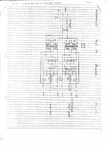
The final stage presents the element of greatest interest: the pilots (4) are identical to the finals (5), which, having a power transistor always has a much lower gain than that of a normal pilot, entails a low impedance of stage input and therefore a low gain of the voltage amplifier stage. By contrast, there are greater problems of extension of the open loop response.
In practice, in this amplifier the very low frequency feedback factor is slightly higher than 40 db, although it tends to increase progressively until reaching the intervention limit of the dominant pole.
As described separately, the assembly of pilots, end caps and temperature sensor at short distance and in close thermal contact allows, with the configuration adopted, an almost perfect thermal stability."
With regard to the latter period, the consideration of the engineer Montanucci regarding the aspect of the operating class of the amplifier in question is very interesting ...
I propose it tomorrow, hoping that my unfamiliarity with the language has not made me write nonsense!
A friend has the A9 and I was looking for general information, the fuse holders having deteriorated, due to the deterioration of the plastic cover.
I found this post and ... also an Italian magazine where the couple C900 and A9 was reviewed.
I agree with the scheme that engineer Montanucci commented on the basis of the test conducted and some of his statements summarized below:
"The circuit configuration of the A9 is classic and complies with the most commonly accepted criteria among the most popular audio designers, based on the absence of electronic current limiters, on the mirror symmetry from input to output and on the adoption of a moderate feedback.
After a mild preliminary filtering (1) at about 150 Khz, the signal is applied to a mirror pair of differentials (2) polarized with just over 1 mA for each branch and equipped with a non-negligible local reaction to lower their gain. A classic symmetric voltage amplifier follows, whose emitter load is not constant with the frequency, being made up of the parallel of a capacitor and a resistance (47 uF / 82 Ohm): this is a "trick", given that the decrease the local reaction to increasing frequency increases the open-loop bandwidth, while making it more irregular.
The final stage presents the element of greatest interest: the pilots (4) are identical to the finals (5), which, having a power transistor always has a much lower gain than that of a normal pilot, entails a low impedance of stage input and therefore a low gain of the voltage amplifier stage. By contrast, there are greater problems of extension of the open loop response.
In practice, in this amplifier the very low frequency feedback factor is slightly higher than 40 db, although it tends to increase progressively until reaching the intervention limit of the dominant pole.
As described separately, the assembly of pilots, end caps and temperature sensor at short distance and in close thermal contact allows, with the configuration adopted, an almost perfect thermal stability."
With regard to the latter period, the consideration of the engineer Montanucci regarding the aspect of the operating class of the amplifier in question is very interesting ...
I propose it tomorrow, hoping that my unfamiliarity with the language has not made me write nonsense!
An externally hosted image should be here but it was not working when we last tested it.
Taking up the topic ...
A friend has the A9 and I was looking for general information, the fuse holders having deteriorated, due to the deterioration of the plastic cover.
I found this post and ... also an Italian magazine where the couple C900 and A9 was reviewed.
I agree with the scheme that engineer Montanucci commented on the basis of the test conducted and some of his statements summarized below:
"The circuit configuration of the A9 is classic and complies with the most commonly accepted criteria among the most popular audio designers, based on the absence of electronic current limiters, on the mirror symmetry from input to output and on the adoption of a moderate feedback.
After a mild preliminary filtering (1) at about 150 Khz, the signal is applied to a mirror pair of differentials (2) polarized with just over 1 mA for each branch and equipped with a non-negligible local reaction to lower their gain. A classic symmetric voltage amplifier follows, whose emitter load is not constant with the frequency, being made up of the parallel of a capacitor and a resistance (47 uF / 82 Ohm): this is a "trick", given that the decrease the local reaction to increasing frequency increases the open-loop bandwidth, while making it more irregular.
The final stage presents the element of greatest interest: the pilots (4) are identical to the finals (5), which, having a power transistor always has a much lower gain than that of a normal pilot, entails a low impedance of stage input and therefore a low gain of the voltage amplifier stage. By contrast, there are greater problems of extension of the open loop response.
In practice, in this amplifier the very low frequency feedback factor is slightly higher than 40 db, although it tends to increase progressively until reaching the intervention limit of the dominant pole.
As described separately, the assembly of pilots, end caps and temperature sensor at short distance and in close thermal contact allows, with the configuration adopted, an almost perfect thermal stability."
With regard to the latter period, the consideration of the engineer Montanucci regarding the aspect of the operating class of the amplifier in question is very interesting ...
I propose it tomorrow, hoping that my unfamiliarity with the language has not made me write nonsense!
Attachments
Thanks! 🙂...just helping to make the image visible
Sorry for the lack of familiarity with the Forum tools... 🙁
I posted - I hope correctly - the image in the previous post which, unfortunately, I cannot delete: I am probably under protection for my few posts ... 😱
- Home
- Amplifiers
- Solid State
- audio analyse' - French made amp?