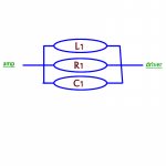
OK, very breifly, the calucated notch filter to remove the 8kHz peak is:
L1 = 0.047 mH
R1 = 21.8 Ohm
C1 = 7.5 uF
All three elements should be in parallel to each other and then this whole circuit in series with the driver. It should be the last thing before the driver, so if you are using BSC, it should be first from the amp, then the notch, then the driver.
Please, keep in mind that this is for single 16 Ohm driver only. If you use it in 4 Ohm implementation - it would have to be re-calculated.
The circuit is most sensitive to the inductance. I've been burnt by using sand-cast resistor, marked as non-inductive. It's inductance was high enough to move the inverted peak of the notch filter away from the peak of the driver. Therefore, either use REALLY non-inductive resistors, or leave enough wire on the coil to adjust L and veryfy by measuered response. The later is only possible if you have the means, so if you don't - pay more for a good resistor.
Vadim
Ok I got the parts, but I have a little problem understanding the connection...
Attached is the schematic , is that correct?
So I have to connect it to the driver, but I have a + and a - .... do I have to make 2 sets per driver? or?
Tnx, and sorry if this is something too obvious!
Erik
Attached is the schematic , is that correct?
So I have to connect it to the driver, but I have a + and a - .... do I have to make 2 sets per driver? or?
Tnx, and sorry if this is something too obvious!
Erik
Attachments
Eric,
It looks correct. The side marked "amp" on your drawing should go to the + of the amp. The side marked "driver" on your picture should go to the + of the first voice coil. The - of that voice coil should go the + of the second voice coil. And, finally, the - of the scond voice coil should go to the - of the amp.
If you would like to use the baffle step correction circuit, it should go between the + of the amp and "amp" label of your drawing.
Vadim
is there any way that with attaching the notch the wrong way you could completely break the driver? Cause I think I just did.... On driver completely dead, other driver working, driver still dead with switching the cable, and a third driver works fine.. damn!
Hi Everyone,
I have 4 of the 16ohm orig versions of the A3, I would like to try and clone 'The One' system using the peerless 3.5 passives into approx 3 litre boxes. Anyway, I really would like to trade straight up my 16s for some dual coil models, I'd be happy to pay for any shipping charges incurred. If anyone is building a larger speaker system and doesn't need the 4ohm config they'd really be helping a bro out.
Vadim, If I am successfull in my quest for some DVCs, maybe you could point me in the direction of some modeling software for the 4ohm notch?
thanks,
Will
Clairaudient state that they do not use crossovers in their speakers, which is their big marketing thing.
This does not mean the same as not using notch filters, or any BSC.
BSC would not be needed on their bi-pole designs, but what about the notch filters? Does anyone know whether they are used in LSA4+4 etc?
This does not mean the same as not using notch filters, or any BSC.
BSC would not be needed on their bi-pole designs, but what about the notch filters? Does anyone know whether they are used in LSA4+4 etc?
BSC would not be needed on their bi-pole designs, but what about the notch filters? Does anyone know whether they are used in LSA4+4 etc?
What do you mean with this?
Hi Everyone,
I have 4 of the 16ohm orig versions of the A3, I would like to try and clone 'The One' system using the peerless 3.5 passives into approx 3 litre boxes.
Will
Considering the external sizes of the ONE: 7"tall x 5.5" deep and 6" wide, the volume can not be much over 2 liters, or am I making a calculation mistake here?
notch filter results
I used the notchfilterthingy today, and to be honest, there was not that much of a difference to my ears. I have been listening and comparing my speakers to a lot of high end speakers at a DIY speakershop in Holland. I keep being left with the idea that there is more possible with the drivers than I am getting out of them. They had a sort of digital dsp system in the shop, and without too much adjusting, they sounded soooo good! There is actually a lot of low in in the drivers, it is a lot softer / less loud than the high. Iam seriously considering making a slightly bigger box (2,5-3,0 liters) for some added bass, and make the inside walls of the enclosure non parallel to tame the mid highs, maybe even dampen the inside of the box...
Oh, BTW, I did not break the third driver, used a faulty connection cable! Grr...
Erik, you are correct, I believe the volume I will shoot for is closer to the 2 litres. As for needing the newer DVCs to get to 4ohm, I think I can just use a different chip amp that will work fine with the 16ohm. At least I will start with that and experiment. I will also try the notch that Vadim suggests. So is 2 litre volume about the correct size then, that is what I gather the more I read up on this?
thanks,
Will
thanks,
Will
apart from the obvious "there is no correct size", about 2 - 2.2liters is the maximum you can achieve with those outside measurements. Having said that, I have finished the two liter enclosures, and I am not happy with the sound, and I am going for something bigger. Especially since I will lose some volume because of the non parallel wall construction I came up with:
And also because I want to experiment a bit with damping the cabinet to lose the harshness in mid highs - highs, and the damping will probably take a bit of the working of the passive radiator away, for which I want to compensate with a bit more volume...
But then again.. I am not an expert on speaker building at all...
An externally hosted image should be here but it was not working when we last tested it.
And also because I want to experiment a bit with damping the cabinet to lose the harshness in mid highs - highs, and the damping will probably take a bit of the working of the passive radiator away, for which I want to compensate with a bit more volume...
But then again.. I am not an expert on speaker building at all...
Although I am not sure how they constructed boxes for The ONE, I think it is likely that the walls inside are parallel but probably well damped with black hole or something. Also I think they use real wool stuffing. I think we should be able to get close if we concentrate with how we damp the cabinets. That being said I will probably eventually use CLD construction to eliminate parallel walls. Similar to Magico Mini but way smaller.
Clairaudient state that they do not use crossovers in their speakers, which is their big marketing thing.
This does not mean the same as not using notch filters, or any BSC.
BSC would not be needed on their bi-pole designs, but what about the notch filters? Does anyone know whether they are used in LSA4+4 etc?
Sorry this was not very coherant.
What I was trying to ask was: Does anyone know whether Clairaudient uses notch filters in any of their designs to tame peaks or nulls?
Hi all
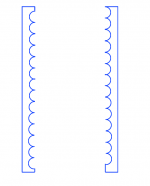
I have been thinking the whole day about non parallel walls in speaker enclosures. I admit, a bit sad, but at the end of the day I came up with the idea as attached.
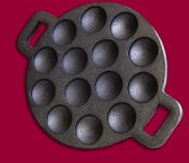
Basically, I want to make round holes (not just the diameter, bit also the inside radius) all over the wall. Basically like what we call in Holland a poffertjespan (see second attachment), but the holes closer together. Especially if the wholes of opposing walls are not aligned, this should result in non parallel wall behaviour of the sound waves inside the enclosure right? Also, it will make the enclosure larger, instead of smaller! What do you guys think?
I have been thinking the whole day about non parallel walls in speaker enclosures. I admit, a bit sad, but at the end of the day I came up with the idea as attached.
Basically, I want to make round holes (not just the diameter, bit also the inside radius) all over the wall. Basically like what we call in Holland a poffertjespan (see second attachment), but the holes closer together. Especially if the wholes of opposing walls are not aligned, this should result in non parallel wall behaviour of the sound waves inside the enclosure right? Also, it will make the enclosure larger, instead of smaller! What do you guys think?
Attachments
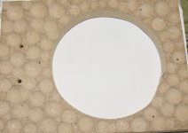
Makes me hungry. Seems like a lot of work and sawdust. Speaking of food, I wonder how lining the walls with cardboard egg cartons would work? Kind of a Red Green approach but might do for proof of concept.
well... if you are talking big speakers it will be a lot of work, considering the small size of the box is should not be that hard... I was actually inspired by the egg cardboard, but I wanted to make the internal volume bigger, not smaller...
OK, very breifly, the calucated notch filter to remove the 8kHz peak is:
L1 = 0.047 mH
R1 = 21.8 Ohm
C1 = 7.5 uF
All three elements should be in parallel to each other and then this whole circuit in series with the driver. It should be the last thing before the driver, so if you are using BSC, it should be first from the amp, then the notch, then the driver.
Please, keep in mind that this is for single 16 Ohm driver only. If you use it in 4 Ohm implementation - it would have to be re-calculated.
The circuit is most sensitive to the inductance. I've been burnt by using sand-cast resistor, marked as non-inductive. It's inductance was high enough to move the inverted peak of the notch filter away from the peak of the driver. Therefore, either use REALLY non-inductive resistors, or leave enough wire on the coil to adjust L and veryfy by measuered response. The later is only possible if you have the means, so if you don't - pay more for a good resistor.
Vadim
Vadim, are you really sure about these values? I am testing it on one speaker now so I can compare it to the other.. and it seems to do more than just remove the 9k peak. The overall volume seems lower and there is a bass reduction as well... Is there any way I can measure the filter to see if it does what it should?
- Status
- Not open for further replies.
- Home
- Loudspeakers
- Full Range
- Audience A3