I have a jigsaw, and could make support frames/gluing jigs to try the bendy-ply types of cabs I suppose
That would definitely work. You could cut the split moulds from msg with a jigsaw, and if they weren't being cut by a cnc that's the exact same tool I would use myself. I'd then probably guess layers of 1mm plywood would be ideal foe stacking up to make the side panel. The only issue I guess I could identify, is the difficulty associated with cutting lots of rectangles out with a jigsaw. Depending on the size however you might be lucky enough to find panels of birch plywood, close to, or even exactly, the right size. On that, you would also need to work out the length of curve needed, but some CAD design, or a piece of string (If you're being old fashioned 😀) could tell you that.
True.
For sure if you laminate your own plywood it can be made quite stiff, requiring nothing more than some no void board scraps randomly glued on edge.
GM
Huh, digging through the old pages of the mini-karlsonator thread, I found this post, form xrk971, apparently he had been asked about this driver before! Back in this post.
Funny how things come around, huh?
I haven't forgotten about this build, just back-burner until a good box is figured out. I'm thinking hollow bottom may end up one of the top choices though, unless a similar enough size can be made to work with horn loading of some sort, for a more "sophisticated" alignment of sorts.
Hello x, would you be able to help or teach me how to sim a Karlsonator or a Nataloss for the speaker shown below? Thank you!
Herewith the speaker T/S parameters
Hi Lemon^2,
I use Akabak to simulate the Karlson and Karlsonator. The code I have developed is not public as it contains a lot of IP that I developed. The outline of how I built the model is described here:
Karlson - Page 10 - diyAudio
And here:
A Speaker that Kicks Butt in Large Spaces - diyAudio
And the very interested DIY'er with enough persistence can make their own model using the guidelines I have posted (one other member has done so that I know of).
However, I am more than happy to run a simulation for you and give you the recommmemded speaker design.
The Nautaloss on the other hand, is a straightforward tapered sealed TL with driver at one end, that can be modeled using HornResp, or any other number of codes. Make a TL at least 3 ft long when spiral is in-coiled. Have it start as wide as driver and taper to a point.
The specific driver you show is a typical soft suspension full range driver probably suited to open baffle. With a rather large Qts (weak motor) and floppy suspension (large 218 liter Vas) says you need a box on the order of 8 cubic feet (huge) to realize the low end bass that it has. If you put it in a Nautaloss of reasonable size, its low end will roll of in ten 200-300Hz range and is suitable for a FAST (2 way with woofer crossover around 300Hz-600Hz).
It won't work in a Karlsonator very well - unless it's a very large one. But maybe that is just as well as the magnet is huge in size.
This may work in a large enclosure that is hollow but completely vented on the bottom toward the floor - no bottom panel and elevated with feet to allow sound to escape. Make a large 8 cubic foot box about 14in wide x 19in deep x 43in tall and elevate bottom by 1.5in to 2in feet with no bottom panel. Mount driver at about 15in from the top (centerline), add stuffing from top to just below driver and held in place by a netting to keep the stuffing from falling. Line 2 of the walls with 2in thick fiberglass or 0.5in thick felt from where full stuffing is on down. You can be creative and make the enclosure non rectangular but keeping the same cross sectional area. Tear drop shape is a good one with curved walls. It's still a very large and imposing speaker but will probably sound pretty good as designed. That can be done without any simulation at all based on the range of Qts and Vas and type of driver that it appears to be. Certain large back loaded horns may work too (like ones by Kohu).
Funny how things come around, huh?
I haven't forgotten about this build, just back-burner until a good box is figured out. I'm thinking hollow bottom may end up one of the top choices though, unless a similar enough size can be made to work with horn loading of some sort, for a more "sophisticated" alignment of sorts.
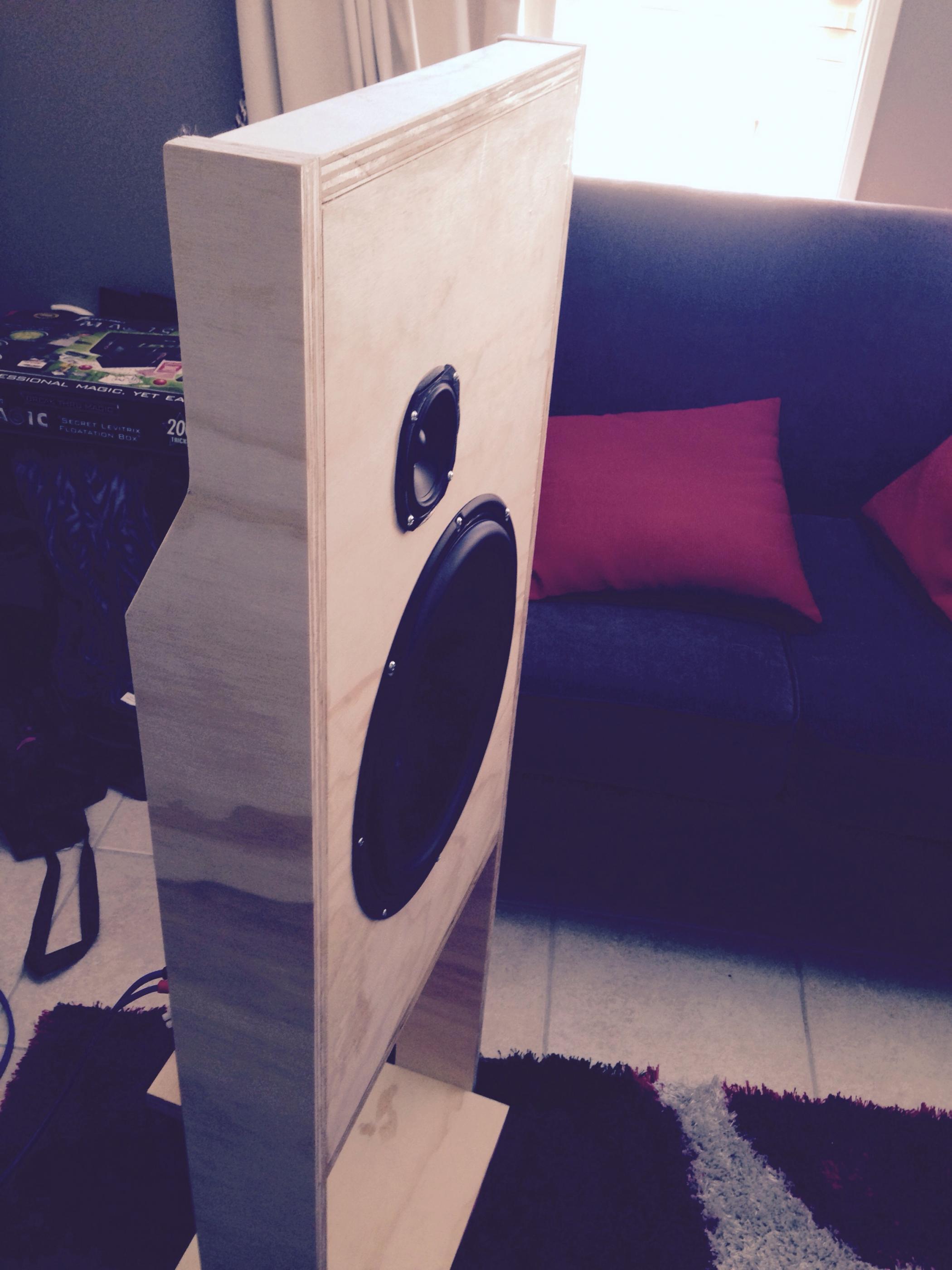
So, I managed to grab a pair of these during the raffle at Burning Amp 2018. They are large, and a simple test session shows that they sound very, very nice open air.
Glad you like them. I had 10 or so on the shelf, and I knew someone
would be attracted to them....

Hey, it's Papa Pass!
Got any recommendations of your own for these? I'm hitting some "analysis paralysis" here!
If all goes well, I'll lug them to Burning Amp next year in cabinets!
Maybe I should just "bite the bullet" and go for some sort of OB like this-
Got any recommendations of your own for these? I'm hitting some "analysis paralysis" here!
If all goes well, I'll lug them to Burning Amp next year in cabinets!
Maybe I should just "bite the bullet" and go for some sort of OB like this-
Last edited:
Alright, this is a little confusing, but I'll reply here to try and keep it all in one place-
So, if I understand right, that would give us something like this-
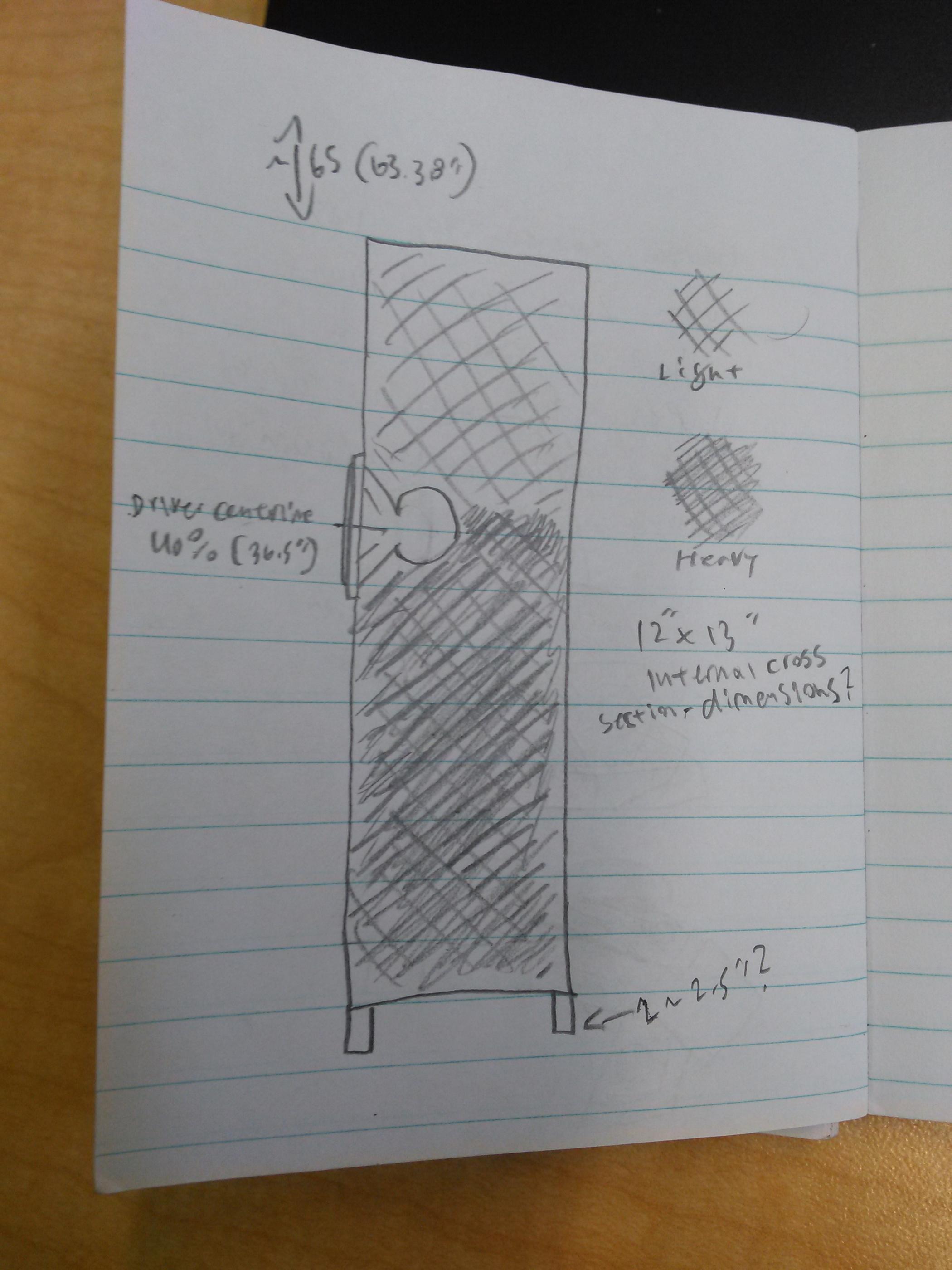
(amateur pocket-notebook sketch)
This is assuming 1"~2.5" feet at the corners, and internal dimensions of 12" wide by 13" deep, and to kinda-sorta roughly make up for the volume of the driver lets just call the height 64" even internally.
Is this about what we're getting at? 1/2~3/4" plywood with some bracing in the middle under the driver might work, I'm thinking.
OK, I took the MLTL sim and turned it into a ~63.38" long x ~153"^2 open bottom TL, raising tuning into the 40s with a ~40% driver offset to minimize frequency response 'ripple' = 36.5" from the bottom, so several inches of elevation to experiment with, which normally is more than enough as you want the floor to preload it a bit.
The sim blue line is with the MLTL's minimal lining of the top, one side and back with the red line a 100% fill with ~1.4 kg of polyfil.
Stuffing just the top half or so won't be enough to damp the lower mids 'ripple' without heavily rolling off the [mid] bass plus the upper half from ~the driver centerline - top is half the stuffing density of the lower half to minimize mid-bass loss, i.e. this is the area where one normally should adjust a pipe's damping whereas a vented alignment is the opposite.
GM
So, if I understand right, that would give us something like this-
(amateur pocket-notebook sketch)
This is assuming 1"~2.5" feet at the corners, and internal dimensions of 12" wide by 13" deep, and to kinda-sorta roughly make up for the volume of the driver lets just call the height 64" even internally.
Is this about what we're getting at? 1/2~3/4" plywood with some bracing in the middle under the driver might work, I'm thinking.
Attachments
Well, while moving things around in the garage I found myself looking at these drivers again, and wanted to give this thread a gentle bump with regards to figuring out a simple but effective cabinet for them. My uncle and I (my family lives with his family) have somehow ended up with a pretty good quantity of plywood (mostly 3/4", some 1/2") in 2'x8' approximate sized sheets- they may come in handy here. I'm still trying to see what a good rectangular box would be for these, assuming I cross them to a subwoofer I don't mind them only needing to reach down to ~80hz or so. Would something like my above sketch still be suitable, or would I be better off making them shorter and wider?
I'm almost inclined to make a pair of cabinets that are ~14" wide, 60" tall, and ~16" deep, with a few inches of space at the bottom that has adjustable feet. Pocket holes and glue for the construction with some braces internally should prove adequate. Stuffing as shown earlier. I'm just unsure.
I'm almost inclined to make a pair of cabinets that are ~14" wide, 60" tall, and ~16" deep, with a few inches of space at the bottom that has adjustable feet. Pocket holes and glue for the construction with some braces internally should prove adequate. Stuffing as shown earlier. I'm just unsure.
At a glance and assuming these are o.d., it will be fine and can even be sealed if an 80 Hz/2nd order [or higher] XO is used.
GM
GM
Hmmm. I think building with a removable bottom panel (easy enough, as I was planning on threaded inserts for adjustable length feet of some sort anyways) for experimentation would be a good idea. I assume stuffing would be more or less to taste, but otherwise as the earlier "sketch"?
I will likely cross them at ~75hz or so for a single sub as the math is easy enough for a Linkwitz-Riley 4th order, unless I go with two subs nearby then maybe I'll cross a bit higher.
I will likely cross them at ~75hz or so for a single sub as the math is easy enough for a Linkwitz-Riley 4th order, unless I go with two subs nearby then maybe I'll cross a bit higher.
Last edited:
Right, though if sealed, then just ~uniformly distributed along its entire length. Close enough, just based on a HR sim not a good plan to go much lower than 80 Hz due to Xmax limit @ 15 W.
GM
GM
Well, sounds like a reasonably sensible use for these then I suppose 🙂
I'll have to draw up some real plans and adjust things as needed to incorporate the tools I have on hand. I just got a pocket hole jig, so looks like plywood with a few internal braces and such would be reasonable. External pocket holes fitted with plugs of a darker wood for contrast, and a simple enough lightly torched and oiled finish should turn out lovely.
Would there be any benefit to mounting the drivers on the ~16" face rather than the ~14" face? If not I'll start sketching something out. Should turn out to be a reasonably economical build.
Yeah, a high Qt, 15 W/2mm Xmax driver isn't going to generate much in the way of acoustic pressure in a large damped box, so minimal bracing to tie/mass load the driver to a sealed cab is sufficient.
Altec recommended a minimum 1.5x dimensional gap to parallel walls and while never seen it published, their cab designs tended to use this with perpendicular walls too, so based on the 330's dims would be ~16" i.d. wide x ~12" i.d. deep.
GM
Altec recommended a minimum 1.5x dimensional gap to parallel walls and while never seen it published, their cab designs tended to use this with perpendicular walls too, so based on the 330's dims would be ~16" i.d. wide x ~12" i.d. deep.
GM
Thanks 🙂
I'll draw something up and start up a cut list to see if what I have on hand will be usable. I have several 2x8' panels of 3/4" on hand and plenty of scrap 1/2" that can be used as well for bracing. I need to cut some shelves for a bookshelf/aquarium stand I built recently so hopefully I don't end up needing to spend much out of pocket.
I'll draw something up and start up a cut list to see if what I have on hand will be usable. I have several 2x8' panels of 3/4" on hand and plenty of scrap 1/2" that can be used as well for bracing. I need to cut some shelves for a bookshelf/aquarium stand I built recently so hopefully I don't end up needing to spend much out of pocket.
- Status
- Not open for further replies.
- Home
- Loudspeakers
- Full Range
- Aucharm UR330B8-11F full range 12" cabinet ideas?