Ha ha 🙂 that is good to know. It is also used in dutch but then frikandel. A good looking used car but full of (hidden) imperfections/a car being a camouflaged accident survivor/a car made of several cars and in all cases also needing costly repairs. Very often the rare GTI or Rallye versions.
Named after the sausage of which no one knows what is exactly in it:
https://nl.wikipedia.org/wiki/Frikandel
Named after the sausage of which no one knows what is exactly in it:
https://nl.wikipedia.org/wiki/Frikandel
Last edited:
If an external dac works then the problem may well be after the dac. Try listening to the output of each of the Jensens in turn. A cheap set of headphone will be more than enough.I connected external DAC to the coaxial exit. Everything works fine, no noise.
I need help where might be the problem.

What I see in the pictures is not a upgrade, is a downgrade.
I'm tired of see faulty devices because the owner thinks that replacing capacitors and op amps improve sound, however, most of all times, instead of better sound, get a faulty device.
If it works, don't touch it.
I'm tired of see faulty devices because the owner thinks that replacing capacitors and op amps improve sound, however, most of all times, instead of better sound, get a faulty device.
If it works, don't touch it.
Thanks for the advice ! I will check.If an external dac works then the problem may well be after the dac. Try listening to the output of each of the Jensens in turn. A cheap set of headphone will be more than enough.
Thanks for the advises! I will shorten the legs of the capacitors where is possible and try to make it more tidy. I will check the regulators in the powers supply. It seems that there is a separate voltage regulator for each channel so it is quite possible to be something from there. It could be very helpful to have a schematic but unfortunately it seems not possible.Of course the only honest comparison is with the very same model from the same year but then unmodded. Anyway it is sad. Good luck, I hope that you can repair it.
The noise on the right channel with the same pace as the flickering can be oscillation of a regulator probably because of adding too low ESR caps at the output of a regulator. Or it can be stray in noise by the ridiculously large capacitors with too long lead wires that function as antennas being too close to emitting electronics.
You possibly are listening to distortion and you like it 🙂 If the CD player will be without complaints chances may be that you will think it has lost its magic. Not my cup of tea, I like tidy and good quality work. I repaired such disaster jobs and nearly always the owner is then not satisfied (with solved complaints!) as he got used to the sound with complaints often paired with strong convictions so it is not rewarding do so.
"Normal" 78xx/LM3xx voltage regulators don't like low ESR/very high value caps at their outputs. In case separate regulators are use per channel you can almost be sure this is the case in that channel. Normally one uses a 10 µF electrolytic cap here with short lead wires and local decoupling further on in the circuit. A bit like the manufacturer did 🙂 Black Gate caps are nice but they're not suitable for use directly after the classic/standard regulators.
As noted, please do not complain the "magic" is gone. You might have the typical strong conviction the device is excellent (because of perceived reputation, boutique parts, higher price) combined with an oscillating so in fact bad performing device in reality. This can be frustrating. An oscilloscope will show you in an instance what is happening. Tools, measurements and basic electrical rules often are enemies of audiophiles that only use ears. "When it sounds good it IS good" 😀
Last tip: only use good quality parts that fit physically and solder the parts as usual in electronics so straight to the PCB without the silly habit of extension wires.
Last edited:
In picture 8890 I think we see extreme high value ultra low ESR caps used after the regulators. First suspects!
The same here and i know frikadel ,i lived 3 years in belgium 😉Ha ha 🙂 that is good to know. It is also used in dutch but then frikandel. A good looking used car but full of (hidden) imperfections/a car being a camouflaged accident survivor/a car made of several cars and in all cases also needing costly repairs. Very often the rare GTI or Rallye versions.
Named after the sausage of which no one knows what is exactly in it:
https://nl.wikipedia.org/wiki/Frikandel
I think merguez in Germany is called wurst (spiced sheep sausage for couscous )
Forgive me Nasitch, but at least a dozen details make me jump when I look at the details of your turntable and I'm not talking about the choice of components, but especially the implementation, I just hope you don't have it not bought too expensive.
The noise we hear in your video is really strange because the frequency is quite high and ripples and looks like two drops of water like a belt slipping on a pulley.
to remove the mechanism, you must first slide the front of the drawer upwards, acting gently so as not to break the plastic flanges.
Once the mechanics are out, disassemble the main PCB to see what state it is underneath because I'm afraid of the carnage and take the opportunity to determine what the shunt is for (white wire on the surface, digital side).
Hi Jean Paul!In picture 8890 I think we see extreme high value ultra low ESR caps used after the regulators. First suspects!
Thanks again for the advises!
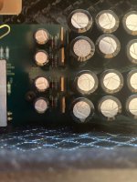
In the attached pictures you can see : 8926 is general look of all regulators,
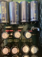
8924 seems to be the powers supply for the right , left channel.
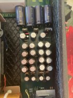
Picture 8925 - power supply probably for the digital part.
I checked the 4 regulators from picture 8924 . They probably power the 2 channels separately because they make 2 identical +- power supplies .
Because I still have not taken out the PCB from the box I measured the voltage on the socket of the regulators.
One couple shows + 55 V -55 V, but the other one : +52 V - 55V, there is +- 3 volts difference.
What I noticed all regulators run warm, but that one that shows +52 V run very hot, I can not keep my finger on it. The capacitors after the regulators , when I touch them on the metal caps , they are also noticeable warm.
Also the regulators from picture 8925 ( 3 pcs , probably for the digital part, also run very hot, I burned my fingers.
I have to probably replace all this capacitors but I do not know what is the original value, before the mode ...
Do you have any other suggestions how to deal with the power supply? Probably the problem comes from there...
Attachments
There is not enough time in my lifetime to correct all mistakes of others besides the ones I make myself so this was it.
Change the PSU board back to original value caps and resolder all joints adding heatsinks to the regs while you are at it. Special attention to decoupling caps at outputs of regulators. Small value and normal industrial quality. Remove all BG that are used for that purpose. Leave the BG filter caps as they are OK at that spot.
BTW first time I hear of +/- 55V in a CD player. Very odd especially as “16V” is printed on the PCB.
Last edited:
I will try to send an email to Atoll to ask them the question, it costs nothing to try.I have to probably replace all this capacitors but I do not know what is the original value, before the mode ...
Thank you very much for the tips !Forgive me Nasitch, but at least a dozen details make me jump when I look at the details of your turntable and I'm not talking about the choice of components, but especially the implementation, I just hope you don't have it not bought too expensive.
The noise we hear in your video is really strange because the frequency is quite high and ripples and looks like two drops of water like a belt slipping on a pulley.
to remove the mechanism, you must first slide the front of the drawer upwards, acting gently so as not to break the plastic flanges.
Once the mechanics are out, disassemble the main PCB to see what state it is underneath because I'm afraid of the carnage and take the opportunity to determine what the shunt is for (white wire on the surface, digital side).
Thanks ! It will be very useful. also for other people.I will try to send an email to Atoll to ask them the question, it costs nothing to try.
Possible scenario is to take out the BG caps, restore the CD200 to nominal state, sell both and buy a nice upper class audioplayer for the money. This merguez will cost again money and time while staying a 16/44.1 device.
I sent the email, we'll see if they respond.
I slipped photos into my email just to make them laugh a little. 🤣
I slipped photos into my email just to make them laugh a little. 🤣
the 160VA ring is only for the output stage, that says a lot ...There is not enough time in my lifetime to correct all mistakes of others besides the ones I make myself so this was it.
Change the PSU board back to original value caps and resolder all joints adding heatsinks to the regs while you are at it. Special attention to decoupling caps at outputs of regulators. Small value and normal industrial quality. Remove all BG that are used for that purpose. Leave the BG filter caps as they are OK at that spot.
BTW first time I hear of +/- 55V in a CD player. Very odd especially as “16V” is printed on the PCB.
Atoll electronics tend to run HOT and I won't be surprised if the output stage is Class A polarized to death.
On the other hand, their enclosures are great for putting something else in there. 😆
I got the impression that there is no active output stage anymore!?!?
The audiophile “coupling caps directly to DAC chip” approach.
Slogan of today: If one sees and mods equipment like it being a musical instrument itself don’t be surprised if it plays its own tone 🙂
The audiophile “coupling caps directly to DAC chip” approach.
Slogan of today: If one sees and mods equipment like it being a musical instrument itself don’t be surprised if it plays its own tone 🙂
Last edited:
Yes, the toroidal transformer is only for the output stage and what I know it really works in class A . I disconnected the big transformer and the unit can be used like a CD transport. Everything works. Only the output stage is off.the 160VA ring is only for the output stage, that says a lot ...
Atoll electronics tend to run HOT and I won't be surprised if the output stage is Class A polarized to death.
On the other hand, their enclosures are great for putting something else in there. 😆
By the way I changed all BG capacitors after the regulators with normal ones ( on the PCB were written the normal values). The big blue capacitors are also already soldered directly to the PCB.
No change. The noise is still there.
The values on the regulators for the analog part are the same + 55 V -55 V, : +52 V - 55V, 1 shows 3 volts less than the others
- Home
- Source & Line
- Digital Source
- Atoll CD200- strange noise