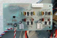
I also see that you have that nice copper "wings" on the side of your pcb. Was this standard with your kit or did you order it separately?
Thanks Ricotjuh.
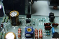
This afternoon I'll start checking that part. I replaced the original 2S330GR with the 2SK170GR (different pin out). I assumed they could work. I think I have some 2SK246GR so I can try them.
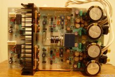
I did the copper fins with a sheet of 3mm thick with the same shape as those used in the original amp. This is relatively easy to do and gives to the pcb a better appearance.
This afternoon I'll start checking that part. I replaced the original 2S330GR with the 2SK170GR (different pin out). I assumed they could work. I think I have some 2SK246GR so I can try them.
I did the copper fins with a sheet of 3mm thick with the same shape as those used in the original amp. This is relatively easy to do and gives to the pcb a better appearance.
I changed the 2SK170 to 2SK246. The amplifier seems to work. 😀
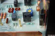
1st Step, I have managed to easily regulate the voltage to 0.7Vdc both channels.
2nd Step, I have regulated 0.021mVdc. Hot the settling dropped to 0.020 ~ 0.019mV. For me it is correct.
3rd Step, the Offset stays very stable in between 0~1mVolt hot. Cold around 5mVdc and then down to 0~1mVdc.
I have left it several hours on measuring everything but I haven´t heard it yet. LED tells me that everything works correctly.
Mosfet maintain a stable temperature, about 47º after one hour. It seems that everything looks good.
I´ll try to connect the outputs on the weekend and listen to it.
2nd Step, I have regulated 0.021mVdc. Hot the settling dropped to 0.020 ~ 0.019mV.
Sorry, I meant 0.021Vdc (21mVdc)
Good to read that you have gotten things going. For me the temperature on the cooling block is certainly 10 degrees Celcius higher (57.6 degrees Celsius). But first do a listening session.
Thanks for your help.
I have a question about Bias. For a first test I'll leave the amp runs with 0.020Vdc (about 111mA, my amp has 0.18ohm resistors) but I would like raise this voltage to 0.036Vdc (200mA).
Will there be any difference in terms of sound or performance?
I have a question about Bias. For a first test I'll leave the amp runs with 0.020Vdc (about 111mA, my amp has 0.18ohm resistors) but I would like raise this voltage to 0.036Vdc (200mA).
Will there be any difference in terms of sound or performance?
For the correct bias, it must be tuned between 200mA and 230mA. That is how it was designed. If they are tuned differently, the transistors work in a different area. From when this is audible, I dare not say. But if you have 0.18ohm resistors, then you have to adjust the bias to 36mV.
20mV is with 0.1ohm resistors.
20mV is with 0.1ohm resistors.
- The working area of the final transistors varied greatly. As a result, it was not possible to set the bias to 44mV for one channel (because the quiescent current must be 200mA and the resistances are not 0.1ohm but 0.22ohm). Because of this I have adjusted the resistance of the relevant channel from 2K7 to 3K9. This makes it possible to adjust this channel to 44mV.
OK, just like you, it has been impossible for me to reach the right voltage (34mV). I was able to arrive (cold) max. 30mVdc on one channel and at 34mVdc on the other. Hot the voltage drops to 22mVdc in both channels. 😡😡
Novice question; How did you calculate the resistance you needed?
Novice question; How did you calculate the resistance you needed?
I do not calculate it. Just trial and error....
I first tries 3k3 but it wasn't enough. Then try 3k9. That worked for me
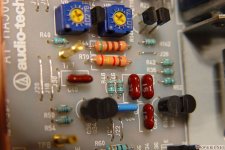
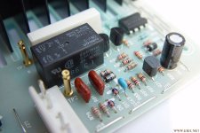
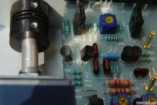
What strikes me is that you have used different types of resistors along the position of transistors 2sc3423 and 2sa1360. (brown colored) At TP7 I see this also. These values are correct too?
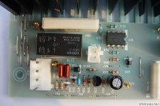
Have you also soldered the smd thermistor to the bottom of the pcb?
Have you also soldered the smd thermistor to the bottom of the pcb?
If you mean brown big resistances (1 or 2W maybe), these are the ones my amplifier brought. They are 2K4 instead 2K7 and 510 ohm.
I had to change some resistances from the kit because it brought very high tolerances (5% in some resistances). I used Vishay resistors (around 2sc3423 and 2sa1360) 100 ohm 1%. On TP7 I change 220r for 640r 1% (remember? 😉)
Yes, this kit comes kit 470r smd thermistor. I guess I was lucky.
I had to change some resistances from the kit because it brought very high tolerances (5% in some resistances). I used Vishay resistors (around 2sc3423 and 2sa1360) 100 ohm 1%. On TP7 I change 220r for 640r 1% (remember? 😉)
Yes, this kit comes kit 470r smd thermistor. I guess I was lucky.
If you mean brown big resistances (1 or 2W maybe), these are the ones my amplifier brought. They are 2K4 instead 2K7 and 510 ohm.
I had to change some resistances from the kit because it brought very high tolerances (5% in some resistances). I used Vishay resistors (around 2sc3423 and 2sa1360) 100 ohm 1%. On TP7 I change 220r for 640r 1% (remember? 😉)
Yes, this kit comes kit 470r smd thermistor. I guess I was lucky.
Lucky bastard

Okay, if all resistors are correct, then you can start with the 2K7 resistor to increase a step. As I described earlier. And then start measuring again on the emitter resistors.

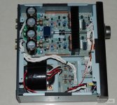
Some more here🙂
Attachments
Lucky bastard
Okay, if all resistors are correct, then you can start with the 2K7 resistor to increase a step. As I described earlier. And then start measuring again on the emitter resistors.
Would not it be better to change the dual output resistors for one 0.1R as indicated by the original scheme?
That is possible, but is certainly not necessary. As long as you fine-tune the bias. Just look at my project. There the resistances are 0.22ohm.
Problem is in the output transistors. These are probably not matched properly and the control area varies.
Those in my kit were even soldered somewhere else. Legs were cut and desoldered.
Problem is in the output transistors. These are probably not matched properly and the control area varies.
Those in my kit were even soldered somewhere else. Legs were cut and desoldered.
Yes, in my amp K2955 and the J554 are recycled.
I don´t know what solution to choose. I need some components so I will order for 0.1R resistors like 3K9 ones.
I'm listening for the first time. It looks good.
Is there any way to adjust the protection circuit? Relays only act from 150mVdc offset. It is definitely a very high voltage for headphones.
I would feel more comfortable if they cut contact with 70mVolt.
No, that is indeed not good. Last time you got your comperator circuit working. So I assume that those values are still correct. Maybe check the values of the Schmitt trigger.
For me, the protection circuit works perfectly well with an offset of 0V DC. If the signal the + 200mV and -200mV exceeds, then the relays fall off.
For me, the protection circuit works perfectly well with an offset of 0V DC. If the signal the + 200mV and -200mV exceeds, then the relays fall off.
Yes, my amplifier continues with the values of the last setting (offset 0~3mVdc, BIAS 0.030Vdc) but I remember that when adjusting it for the first time I could verify that with 150mVdc the relays acted.
That's why I was thinking if it would be possible to adjust the cut-off value.
Nice sound, I'm impressed. I did not expect it to sound like that. Very interesting.
That's why I was thinking if it would be possible to adjust the cut-off value.
Nice sound, I'm impressed. I did not expect it to sound like that. Very interesting.
- Home
- Amplifiers
- Headphone Systems
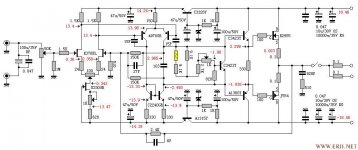
- AT-HA-5000 schematic