Resolved with a clock switch- must have been an inadequate solder on the adapter on the original NDK clock... except I wonder why it worked fine for spdif? Just happy it's working now... and also appreciative of what Ian has created and what it has contributed to my system's sound.
Correction- it is NOT resolved.
However, both clocks are working fine and all sounds good via spdif (to other DAC) via either optical or RCA.
I was suspecting the is2 to PCM board might have an issue getting 16 bit music to the AD1865 DAC.
The HDMI out to the i2s to PCM board:
*Works fine for 96/24
*Works fine for 44.1/24
*DOES NOT work for 44.1/16 - get digital noise with music in background.
This is in spite of the "good i2s signal" LED being on for the 44.1/16
I tried the "half speed" jumper on the i2s to PCM board and no change.
However, I just tested another HDMI i2s source (Pi2 Designs Pi2AES + Raspberry Pi with Volumio) with 44.1/16 to the HDMI Receiver/is2 to PCM/AD1865 and it worked fine.
I also tested different HDMI cables.
It seems the issue is narrowed to the HDMI output for 16 bit music from the FifoPi/Transport Pi.
Any ideas for a fix? Thanks.
Last edited:
Hi JCMcNeil,
No worries, I'm here to help.
I see the problem is that your DAC doesn't support true 16bit mode. I have a solution for you.
FifoPi has a 16 to 32 lossless conversion feature. Please enable it by setting the jumper switch. I believe it can solve your problem.
Please let me know if you have a update.
Regards,
Ian
Not comparable to how it sounds in real live, but it gives an idea 😉
Ready to make the connections 🙂
The power switch LED is a bit too strong so I have to come up with something about that.
The Raspian still sounds like a Swiss timepieceso as far as I'm concerned, this conversion is more than successful 🙂
OMG! This is simply beautiful. This is the most WAF compatible DIY Streamer/Player I have seen. WOW! Take a bow!
Could you share a laundry list of all the parts and software you used? Not all of us are PC literate. Thanks.
The DAC has it's own batteries (2 x Enix 3.7V), I just need to feed OPT IN (top left). No headphone amp needing power as it doesn't have one, zero amp involved since amps colour and distort. It outputs directly from the FPGA DAC for max Transparency and Resolution, no amps:
Which DAC is this?
Topping D90 is the lowest price AK4499 flagship DAC. For evaluation, I bought one months ago . The sound quality is good for me. But still not as great as I expected.
The modification job is not that easy because the HDMI connector pins are very small. I'll implement this feature in my new HdmiPi MkII transmitter design very soon.This feature may apply to Topping D70 and many other I2S/DSD DACs with HDMI input.
Awesome Ian, I was thinking of getting the Gustard X16 as soon as shipments from China to India start. It too has I2S (LVDS) inputs and measures well according to ASR (though measurements only mean so much).
Last edited:
Which DAC is this?
Sorry, I am going to refrain from discussing my Chord DACs going forward as it's too off topic, de-rails the thread and complete paradigm shift in thinking as it's a modern FPGA DAC, not traditional off-the-shelf DAC.
I only discussed as someone was helping me plan out my power requirements so I wanted to describe that I had no need to power a headphone amplifier and my DAC had it's own power supply. Thus I can obtain sufficient power with just a single 18650 if needed.
I just want to focus on Ian Canada projects as I'm going through the trials and tribulations grinding away at this time.
Here's a link to find more info, but I'm not going to discuss here anymore:
DACs - Chord Electronics Ltd
Last edited:
I see the problem is that your DAC doesn't support true 16bit mode. I have a solution for you.
FifoPi has a 16 to 32 lossless conversion feature. Please enable it by setting the jumper switch. I believe it can solve your problem.
Regards,
Ian
Thanks, Ian
I assume you mean switch 2 on SW1 on the bottom of the FifoPi?
If so, I had already tried turning that on but got silence on 16 bit songs instead of noise. Sorry I didn't mention that in my posts.
Also, as I wrote, and in case it's relevant, the DAC plays 16 bit songs correctly from a different HDMI source: Pi2 Designs Pi2AES.
Last edited:
What would you guys do to best power the fifo in my case.
So I am Pi less and feed 3v3 LT1963 with 1.5f supercap into clean fifo side...LDO bridges are jumpered. Salas L adapter powers 5v into Fifo dirty side which also powers the Receiver Pi via GPIO.
I intend to improve the digital side of the Fifo. I only use one clock.
I have a Salas Reflektor D to use and some LT3042.
Should I just power into Fifo clean with Ref D 3v3.
Or isolate power to clock and feed Ref D straight to that and use a LT3042 at 3v3 into fifo clean side.
Or vice versa....Ref d to fifo clean and lt3042 to the clock.
Or indeed use TPS7A4700 in place of 3042.?
And I have the aforementioned 1.5 supercaps and also some 310F Maxwell that I havent used yet. That would be a diy set up..Not U conditioner.
Just wondering where to apply the Ref D really.
Sorry, I am going to refrain from discussing my Chord DACs going forward as it's too off topic, de-rails the thread and complete paradigm shift in thinking as it's a modern FPGA DAC, not traditional off-the-shelf DAC.
Here's a link to find more info, but I'm not going to discuss here anymore:
DACs - Chord Electronics Ltd
Thanks. I had no idea it was a Chord. I thought it was a DIY DAC that you built, that's why I asked.
Thanks. I had no idea it was a Chord. I thought it was a DIY DAC that you built, that's why I asked.
No worries, I wish it was a DIY DAC since I probably ended up paying a good amount just for the aircraft aluminum case (CEO's idea). I prefer to just run with a PCB.
Not fond of Chord as a company. I'm glad they are moving on from their current "out of touch" CEO. I'm only fond of the DAC Designer whom is a Consultant and not direct employee of Chord.
Anyways, back on track with Ian Canada project... My A123 26650 with tab arriving Tuesday. Never been more excited to receive a battery...
18650 specs:
- Impedance (1kHz AC) Typ: 12.6 mΩ
- Energy @ 23 oC: 3.63 Wh
- Impedance (1kHz AC) Typ: 6 mΩ
- Energy @ 23 oC: 8.25 Wh
Last edited:
I really dislike the super random brand name 26650 battery holder, so I would move heaven and earth for the 'tab' option. The plastic melts so easily when trying to directly solder wires to the tips. It's like the most unhealthy thing to breathe, so glad to not have to re-visit. Relieved also to be removing a potential bottleneck.
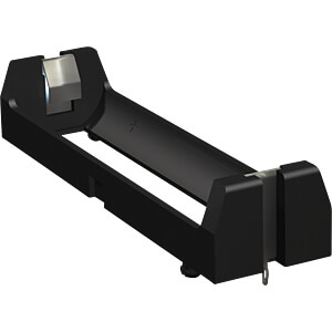
I wish Keystone would make some solid 26650 holders one day, so I can implement on the MKIII. They have one for the 18650, but unknown why they don't have a 26650 available:
I'm upgrading the 5mm terminal blocks where needed with Keystone since they are beefier and handle higher guages:

The color matches my solid core silver power wiring so that's kind of kewl...
I wish Keystone would make some solid 26650 holders one day, so I can implement on the MKIII. They have one for the 18650, but unknown why they don't have a 26650 available:
I'm upgrading the 5mm terminal blocks where needed with Keystone since they are beefier and handle higher guages:
The color matches my solid core silver power wiring so that's kind of kewl...
Last edited:
Some more pictures of the final result, also the grounding improved because I did not realize that the StationPi has 2 different earth screens (TP1 and TP2), 1 specifically for the RPi and 1 specifically for the right side where the FifoPi and the TransportPi house, the star earth point is now on one of the metal inserts that are pressed into the bottom as standard.
Nice mixing in of your DIY thought process with photos. It might be beneficial down the line when I'm able to focus on the desktop build.
A123, just be careful soldering the batteries to the LiFePo4 board. Be sure to put some sort of tape over all of the exposed solder points beside where you will solder the positive side of the batteries. If you touch any of these with a battery or the iron or the solder you may let out some magic smoke. I've soldered 90 batteries into LiFePo4 boards and have not had an issue but always use at least two layers of suitable tape over the bottom of the pins. Minimum 65w iron will get the job done, but it is easier with 80w.
@acg. Great tip, cheers. I'll do that. I'm not comfortable working with tabs on the MKIII at this time, so will stick with the battery holders. I won't be soldering directly onto a battery tab for that project, but I can apply this tip now to my current project. So I will make sure to double up on the tape for both projects just to be on the safe side. In no rush to start the MKIII project since I'm just laying the foundation for the ReclockPi for the 2nd half of 2021, so I can slowly take necessary precautions at this time.
I have already experienced the magic smoke since I fried a BMS and 18650. No worries as I have spares for experimentation. Since this is a portable project, space is tight and it's easy to make a mistake somewhere. Especially more difficult with solid core wires since they are so stiff. I don't know what went wrong as it's a straightforward process, but since soldering pin holes are so close together it's easy for just the tiniest of solder to spill over. I also had to remove the 40 GPIO pins on the BMS one by one as the space is so tight.
That's why I started a 2nd prototype... To learn from my noob mistakes and apply what I learned from the 1st prototype. I hope I can add terminal blocks to the BMS. There's no spacing size specified so hope I ordered the correct terminal blocks. It's such a pain to solder directly to the PCB. The pin holes get contaminated with plastic and soldering dust so easily. The 2nd prototype should be much cleaner in aesthetics and wiring. The wildcard is the 26650 with tab in the mix. As long as I can overcome that, it should turn out nicely into my dream portable music server (minus "pulsar" clock for now).
Does anyone know if I use a heat gun to heat shrink a single 26650 with tab would that cause harm to the battery? Heat gun not powerful enough to harm? I feel more comfortable if I heat shrink the parts of the tab where exposed and the battery endpoints.
Last edited:
I'd love to get everyone's view on this guy. I don't know why he showed up on my YT feed but I subscribed to him just to see what he says. I also see that he sells some mighty expensive equipment.
i2S and outboard Master Clock Generators. Whats the deal ? - YouTube
i2S and outboard Master Clock Generators. Whats the deal ? - YouTube
Seems more fashion oriented than fact based. maybe an offshoot of Qanon?
The Quartz crystal vs mechanical oscillator?? If he is talking about MEMs oscillators they are good but not in the same class as a premium crystal oscillator for stability or phase noise/jitter.
Also USB uses I2S internally to talk to the DAC chip.
The whole thing reminds me of someone I knew in college warning me against salt because it has sodium and chloride in it.
Try removing the contacts from the holder before soldering and clip back in afterwards.
Okay, thxs. I'll keep it in the back on my mind as an option when I start the MKIII project.
For the portable project where I have to solder wires directly on the tiny contact points of the holder, this would be great if I can remove the contacts from the holder. But if I re-visited, I would just use a Keystone holder going forward:

I have the Keystone holder on it's way as I need a 26650 charging solution when I start on the MKIII. I already have a spare BMS so will solder wires to Keystone battery holder to load up the 26650s before I plug into the MKIII for the first time.
For the desktop MKIII project, the soldering takes place under the board and on the soldering pot of the PCB so I'm not sure yet if removing the holder contacts is necessary. But I'm keeping it in mind and curious also on removing the contacts from the holder.
Since I feel more comfortable now leveling up from my noob stage, I think I would of preferred the tab route on the MKIII. But it's good also to play it safe at this time and just get things up and running and then optimise down the road.
Last edited:
I should of ordered this Keystone 26650 holder also to experiment if I can get it working with the MKIII. But my focus is solely on the portable project at this time, no attention given to MKIII unfortunately.

If I can bend down the tabs maybe it would fit the MKIII on one side. I guess can also try soldering tips to the tabs.
I'll add to Mouser project for next order.
Link to Keystone 26650 battery holders:
Sleds-Holders for 26650 lithium-Ion batteries from Keystone Electronics
Link to Keystone terminal blocks:
Terminal Blocks, Modular PCB Terminal Blocks: Keystone Electronics
Terminal Block, Modular, Screwless, Push-Button: Keystone Electronics
EDIT:
There are tips:
thru hole mountable loop type pcb test point terminals
thru hole mountable slotted pc test point terminal
So will research and hopefully experiment before starting the MKIII project.... Would be great to bypass the current random brand name 26650 holders if possible. I feel more comfortable utilising Keystone.
Last edited:
yes, the keystone is the best of the bunch. as mentioned, you can remove the terminal, solder to it, then reinsert it, to avoid heat damage.
- Home
- Source & Line
- Digital Line Level
- Asynchronous I2S FIFO project, an ultimate weapon to fight the jitter