Asymmetric speaker system.
Satellite subwoofer systems are an effective solution to the problem of reproducing the bass frequencies in a speaker system without using the space that the more common two speaker system uses.
Having built a satellite subwoofer system in the past, I was able to appreciate the decent performance afforded by even a rudimentary system, however the placement of the subwoofer on the floor proved problematic.
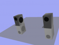
One solution I have been looking at is the placement of the subwoofer adjacent to or inside the enclosure of the satellite speaker, either in a forward firing position as shown in the 3D graphic here or as a sideways firing driver, since directionality is less important for the lower frequencies.

What are the possible problems that could occur in such a system, and also what sort of dummy load is to be used if only one subwoofer driver is to be used - for example attached to the left speaker which will have an impedance of 8 Ohms for example?
Some info here, but I have not found answers yet to my questions.
All You Wanted To Know About Subwoofers
Overview of 2.1 (Satellite/Subwoofer) Spe - Maxim Integrated
Satellite subwoofer systems are an effective solution to the problem of reproducing the bass frequencies in a speaker system without using the space that the more common two speaker system uses.
Having built a satellite subwoofer system in the past, I was able to appreciate the decent performance afforded by even a rudimentary system, however the placement of the subwoofer on the floor proved problematic.
One solution I have been looking at is the placement of the subwoofer adjacent to or inside the enclosure of the satellite speaker, either in a forward firing position as shown in the 3D graphic here or as a sideways firing driver, since directionality is less important for the lower frequencies.
What are the possible problems that could occur in such a system, and also what sort of dummy load is to be used if only one subwoofer driver is to be used - for example attached to the left speaker which will have an impedance of 8 Ohms for example?
Some info here, but I have not found answers yet to my questions.
All You Wanted To Know About Subwoofers
Overview of 2.1 (Satellite/Subwoofer) Spe - Maxim Integrated
Last edited:
A subwoofer wil always use active filtering and extra power amp
Active filtering includes mixer for L and R channel
Try to use passive filtering for both sub and satellites, and tell.
But, for emergency cases, you can use asymmetric: the amplifier channel used for both sat and sub will be stressed more.
BUT, i don't see its utility: you say "common two ways"...but if it was three ways ?
Common sense says: woofer for bass, midrange for...mid and tweeter for treble.
The satellite subwoofer system I built was hooked up to speaker outputs of a CD-Casette player, by cutting the speaker wires and re-routing the wires to speaker terminals which I fixed to the case. It worked well enough, but having 8 Ohms impedance on one side and two 8 Ohm loads in parallel on the other side. I detected no soound level difference on the left/right speakers, and the amplifier section survived several years usage.
So this was a single amplifier circuit driving two speakers as well as a subwoofer (actually an 8 inch speaker in a box) hooked up in parallel to the right or left speaker terminals.
Apparently the commercial systems are different, using two amplifiers ? This one for example puts out 14 Watts:
LOGITECH Z213 2.1 PC Speakers Deals | PC World
The other point I want to make is that these systems sound very complete- the bass is certialy adequate for listening, and even You Tube music sounds goodeven though it is low resolution.
Has anyone come up with something remotely similar? All you need is to hoist the subwoofer next to the satellite speakers and there you have it. It would be more comact to house the subwoofer and satellite speaker in one box to cut down the number of boxes you have to carry around or mount on stands or a wall or bookshelf.
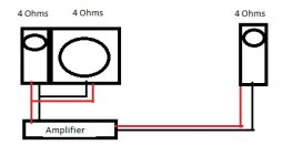
Satellite Subwoofer wiring
So it comes down to how to connect the subwoofer driver without damaging the amplifier or quality. Will this work?
Any additional components to be added - resistors, inductors, dummy loads etc?
But, for emergency cases, you can use asymmetric: the amplifier channel used for both sat and sub will be stressed more.
So it comes down to how to connect the subwoofer driver without damaging the amplifier or quality. Will this work?
Any additional components to be added - resistors, inductors, dummy loads etc?
Attachments
Last edited:
Updated design with side firing woofer
I updated the design: the earlier design looks too cumbersome.
I have only once seen a commercial system with a side - firing woofer, and it seems like a good idea to save space and preserve appearance. The woofer will be probably 8 inch and the front speakers will be full range. There is a the motivation to add a tweeter. As before, the asymmetric loads on the amplifier is what I am concerned about.
Attachments
Looks like there are some out there:
Canton Introduces Four New Speakers in its Karat M Series: BigPictureBigSound
Can side firing woofers be high end? - YouTube
Paul says "Make sure your designer knows what the hell they are doing". Thanks Paul.
Canton Introduces Four New Speakers in its Karat M Series: BigPictureBigSound
Can side firing woofers be high end? - YouTube
Paul says "Make sure your designer knows what the hell they are doing". Thanks Paul.
Last edited:
I would not suggest a dummy load of any kind for a transistor amplifier. That's just wasting power. The amp channels don't care if they're loaded differently, but you don't want the impedance to get too low.
If you want to stick with a passive system, a more common approach is to use a dual voice coil woofer for the bass section. Both left and right amp channels can then be used on a single woofer.
A passive crossover on the various speakers will prevent the impedance from dipping too low and also improve power handling/distortion performance.
Can I get a rough estimate of impedance using a multi-meter, that is, 8 Ohm speaker will measure 6 Ohms across its terminals.
For a raw speaker, yes.
For the combined effect of multiple speakers with crossovers, no. What you are missing in this scenario is impedance at various frequencies. When you measure resistance with a meter, it's DC (0 Hz), so all you see is the resistive contribution of the speaker/crossover at the lower end. There are also reactive effects, but that's a more complicated topic.
If you try to measure impedance the old-school way (voltage divider method) with a signal generator, resistor, and multimeter, you'll need to ensure that your meter has decent accuracy across the audio range. Many don't.
Hopefully you're not taking any of this as discouraging. Many people start out with minimal testing abilities, but still have fun and produce speakers that are useful and enjoyable as long as they respect some basics and are willing to tinker a bit.
It sounds like you got away with the setup you ran previously, where maybe you didn't use a crossover at all? Assuming both your satellite and extra woofer were 8 ohms, the combined load was only 4 ohms, which most transistor amps will handle fine. If the amp doesn't get hot or have other problems, you're typically OK.
Last edited:
Thanks Matt. I measured the resistance values across a set of heavy small speakers I salvaged from a PC speaker unit. Both say 4 Ohms on the back but the readings on my multi-meter say 3.7 Ohms for one and 4.2 Ohms for the other one. I imagine the loudness of one will be more than the other, in fact I have measured this unbalanced volume with another speaker I had.
Stereo Review magazine used to state in its test results: so many Ohms impedance at x kHz and another lower value for lower frequencies.
How about testing current flow across the speakers while playing music? No I am not discouraged (thanks for the concern) but I am wondering can the multi-meter be used in any way to solve this problem?
I could check this yes.
Stereo Review magazine used to state in its test results: so many Ohms impedance at x kHz and another lower value for lower frequencies.
How about testing current flow across the speakers while playing music? No I am not discouraged (thanks for the concern) but I am wondering can the multi-meter be used in any way to solve this problem?
If the amp doesn't get hot or have other problems, you're typically OK.
I could check this yes.
I'm not sure if you are talking about a woofer and tweeter out of one speaker (the left, for example) or two woofers from different speakers (left and right). As with all electronic devices, there's going to be some drift from unit to unit. And, resistance or impedance alone isn't going to accurately predict loudness.
Measuring current is going to have the same frequency/accuracy issues with a typical multi-meter. Also, the fluctuations in music are much too rapid to accurately measure with a typical multi-meter. You need a signal generator (standalone or PC based) to provide a sine wave, which is much easier to measure.
The basic process for measuring impedance with a multi-meter is shown here:
Loudspeaker impedance measurement using a multimeter and 2 resistors
If your meter is accurate across the frequency range where you want to test, you will only need to calibrate once, instead of at each frequency.
There are also ways to measure impedance with a PC sound card. REW (Room EQ Wizard) is the software that is often used. This will be much faster if you need to take multiple measurements. I don't use this software, but there are many posts describing its use on diyAudio.
Impedance Measurement
Comb over?
When blending subs evenly to satellites, should I be using a quarterwave calculation to arrive at optimal distance and frequency roll off, as I would in spacing speaker drivers to avoid comb filtering?
Example: if my satellites are 10 feet apart, centre to centre, should my sub be rolling of at about 28 hertz?
Or should I calculate based on the greatest distance between the sub and a satellite?
- Home
- Loudspeakers
- Multi-Way
- Asymmetric Satellite Sub woofer System