I did it using both programs: PCD and acoustic measurements in OmniMic per the instructions and adjust for delay there. I struggle with the PCD program as it does not display correctly on my machine so in the end I rely on OmniMic
Although I have not used PCD, I wouldn't be asking it to adjust the offset if you didn't move the mic during the measurement, because the delay would be included in the measurement. I'd set the Z offset on both to be 0. Would you agree bullittstang?
It's compensating for their different acoustic centers. So yes, you would use a Z offset in PCD.
I would think your 1.22 inches is very close.
How does you phase look using this new Z for mid and tweeter? DOes the same XO you had in the previous graphs look better or worse? Or were you able to adjust the XO and get a better curve phase relationship? If so, post that.
jimbones - have you tried WinPCD? Very close to PCD, but written to be more compatible with Windows. or Xsim, I use all three but typically prefer Xsim because of it's simplicity, graphic nature and the ability to make "any" XO design you want and see it results immediately.
Thanks for the feedback. I will certainly do that. I only had enough time last night to get the z off set. I have not tried the WinPCD or XSIM but will look into it. I'll post this weekend. Thanks much for all your help.
If you have any problems, post it up and I will try to help as I'm sure others will chime in too.
Looking at PCD, I wouldn't do this unless I was using calculated minimum phase data derived from the response data. The additional excess phase due to the delays included in measured data shows the real situation. Compensating this can return the measured data to minimum phase (notwithstanding the effect of secondary delayed sources).It's compensating for their different acoustic centers.
As long as he is using OM, it develops it's own phase comparison (not exactly sure the technical terminology, but you can read the FAQ's in OM). I've used straight OM data (as long as you don't move the mic and use all the same settings to gather all the FR data) and it has worked as well as minimum phase for me numerous times.
If you are using SPLtrace or similar and using manufacturers data, then yes, you need to adjust for BSC and baffle effects within Jeff B's other software and then take Minimum Phase in order to have an accurate and usable PCD simulation.
I believe the OP is using OM and measuring mounted in cabinet as I said above, unless I missed something (which is possible)
If OmniMic can retain a reference for the time of flight between driver measurements then the measured delay can be used. This might be indicated by looking at the relative phase plots showing that one wraps faster than the other. This kind of phase shift wouldn't be due to the drivers alone.As long as he is using OM, it develops it's own phase comparison
In this case the delay can be added in manually (have PCD do it for you).If you are using SPLtrace or similar and using manufacturers data, then yes, you need to adjust for BSC and baffle effects within Jeff B's other software and then take Minimum Phase in order to have an accurate and usable PCD simulation.
As long as he is using OM, it develops it's own phase comparison (not exactly sure the technical terminology, but you can read the FAQ's in OM). I've used straight OM data (as long as you don't move the mic and use all the same settings to gather all the FR data) and it has worked as well as minimum phase for me numerous times. <Using OM and used it in my original design the same way>
If you are using SPLtrace <yes>or similar and using manufacturers data, then yes, you need to adjust for BSC and baffle effects within Jeff B's other software and then take Minimum Phase in order to have an accurate and usable PCD simulation.
I believe the OP is using OM and measuring mounted in cabinet as I said above, unless I missed something <mounted on flat baffle>(which is possible)
response embedded
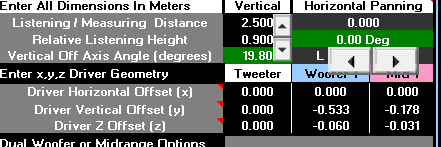
So I have only included the Z offset into PCD. Not sure if I did it correctly but the woofer acoustic center is 60mm behind tweeter and the Mid is 31mm behind tweeter. i did not do the vertical offsets. Not sure how that is done but I measured on center of tweeter. so i guess i would enter negative values in mm for mid and woofer (to thier respective centers). I will mount the tweeter with the 31mm offset now
Attachments
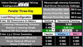
That looks good, you will need to X and Y so when you see phase the program understands what it is "seeing" from the uploaded FR file from OM.
X is the distance right or left of center, so you are centered on baffle it will be "0".
Y is teh distance (in meters) from the listening (or in this case measuring) axis. SO measure down from the tweeter center (assuming that's your measurement axis) and put in (negatively) how far down the mid and then the woofer are from the tweeter center.
Once done, put back in your original XO design and see what the FR and graph look like. I would assume so issues, since you didn't like the sound, but it will give you a starting point. Then you can start modifying to a XO that will work with your new driver(s).
If OmniMic can retain a reference for the time of flight between driver measurements then the measured delay can be used.
No, OmniMic doesn't retain phase reference, it always references to the peak in the impulse response -- that's because it doesn't get a look at the signal that feeds the speaker so doesn't know when it got applied, hence it can't tell how far away the speaker is.
What I've been doing for a while now is taking three UNSMOOTHED measurements for each pair of adjacent drivers (or driver types) after they are mounted in the cabinet or panel. For example, for a 3-way, I collect a FR (with phase!) of the tweeter alone, then of the tweeter+midrange connected in parallel and playing together; then of the midrange alone. Repeat for the midrange and woofer pair (you already have the midrange-alone response for that pair). Then bring all the responses into XSim and toss together a model of just the two drivers connected in parallel to the 'power amp', and load the 'alone' responses into the driver objects (set them to not add any smoothing). Load the response taken from 'both together' into the 'from file' curve (no smoothing again), and in the "Tune" window of the lower frequency driver, adjust its 'mod delay' until the simulated response of both drivers together matches the measured response of them both together. The curves should be nearly an exact match, other than maybe a little noise.
When you do the woofer/midrange pair leave the delay of the midrange to where it was adjusted just above, and adjust only the delay of the woofer in the simulation for a match to its measured 'both' curve. Leave those delay values in your crossover simulation (and use measured curves for the impedances of the drivers), and you should get very accurate results for your setup. After you've done it a few times, it is actually a really quick process to do, even though it's not so quick to describe!
That is, accurate for that mic position! To really see what's going on, I do the same process at a number of off-axis mic positions. In the crossover design simulation, then just have separate driver sets for each mic position, and drag the ones of interest over to connect them to see what the response will be in that direction. Like this --
@bwaslo you explained it 20 times better than me and made it much simpler. Thanks, I and the OP thank you!
Sent from my iPhone using Tapatalk
Sent from my iPhone using Tapatalk
Thanks Bill for clarifying OmniMic's constraints. Simulating the delay would be appropriate.
Apologies to bullitstang if you knew this all along. I use a measurement system that times measurements and I don't have the need to find acoustic centres.
Apologies to bullitstang if you knew this all along. I use a measurement system that times measurements and I don't have the need to find acoustic centres.
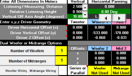
It's in Meters so unless you have a room sized box I think you are a little high on the Y figures? Maybe 0.53?
Sent from my iPhone using Tapatalk
Sent from my iPhone using Tapatalk
I understand completely, took me a dozen designs to get it right on the first time, very easy mistake to make, but luckily it's easy to fix.
Sent from my iPhone using Tapatalk
Sent from my iPhone using Tapatalk
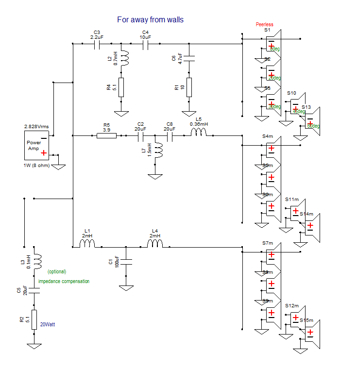
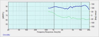
OK so I tried lots of different fr points, slopes, attenuation etc. This was as "smooth" as I could get it. Ive attached info on the xo values with the Fr and phase graph. Thoughts?n Keep it clean ha ha😱
Attachments
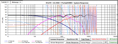
Did you convert your FR data to minimum phase? It doesn't look like it to me from the graph... or maybe you did but didn't normalize the data first (I use the spltools splview to make sure the data goes down to 20 Hz for all drivers (it basically extrapolates down at 12db / oct to fill in the missing data)
Tony.
Tony.
- Status
- Not open for further replies.
- Home
- Loudspeakers
- Multi-Way
- assistance with 3 way crossover