I meant: Rect > bypass cap > RCRC > LM317 > bypass cap > decoupling cap.
RCRC is resistor, cap, resistor, cap
🙂
Hello
Oups... my error.
I'm not as good to read english than reading french.
Bye
Gaetan
Last edited:
Hello
there is maby beginers who read this thread and could not go into very much more than the basic schematic gived by Hugh.
If the power supply is not more complicated than the amp, and the parts or substitutes readily available, then this should not be a problem - especially so as boards or board designs are intended. I think that the hardest thing is sourcing all the right parts, in all the right sizes. If you can, design the supply with as many of the same parts as for the amp. The assembly with a labeled board is straightforward.
I like these simpler DIY projects as learning tools to try some different things. If others like to do the same, this may be a good reason to have some flexibility in power supply choices.
Sheldon
That's no fun. You just took all the fun out of life Hugh.
Life no longer has any meaning any more.
🙂
One other route we haven't discussed is an SCR-based series regulator. The one in the link below is the idea but I saw a super-simple schematic somewhere... Just for giggles I guess.
http://www.discovercircuits.com/Andy/SCRReg.pdf
- keantoken
Life no longer has any meaning any more.
🙂
One other route we haven't discussed is an SCR-based series regulator. The one in the link below is the idea but I saw a super-simple schematic somewhere... Just for giggles I guess.
http://www.discovercircuits.com/Andy/SCRReg.pdf
- keantoken
Member
Joined 2009
Paid Member
My vote continues for simplicity. I like the cap multiplier, but I hadn't thought about putting an integrated regulator in the psu and positioning it back from the output so that the signal path doesn't get too close to it. Nice.
Member
Joined 2009
Paid Member
I know this is out of sequence as we're talking 'power supplies' but I got a little question on the amplifier that's on my mind...
The bias set up. We have 3 diodes because it is simpler than a Vbe multiplier. I have only used the latter and find that it's easy to mount a transistor on a heatsink. How do you mount 3 diodes on a heatsink ? - would we actually be better off with a Vbe multiplier ?
(Either way, I'd want to keep a resistor in the string so that we can 'set' the bias current)
Member
Joined 2009
Paid Member
not a bad idea. I used superglue to put two heatsinks back to back for my TGM amp. When I looked into it I found that there is more than one kind (ethyl and methyl) and one of them is better over temperature than the other (can't remember which one).
would we actually be better off with a Vbe multiplier ?
Hey Gareth,
I prefer a vbe multiplier. Less hassle, not many more parts and the ability to set the idle current high or low.
The bias set up. We have 3 diodes because it is simpler than a Vbe multiplier. I have only used the latter and find that it's easy to mount a transistor on a heatsink. How do you mount 3 diodes on a heatsink ?
Wire some transistors as diodes?
Sheldon
We could do that, but we would have to increase VAS bias which would decrease the effectiveness of the bootstrap (lower impedance) because of losses through the resistors (unless we use high value resistors).
- keantoken
- keantoken
John,
I once did a comparison between the Vbe multiplier and the diode string.
For some reason I cannot fathom, with the same circuit, same bypass cap, etc, the diode string sounded a tad more refined.
I suspect there is less variation in voltage with current change.
Anthony,
I do enjoy your humour! Or perhaps at 45 degrees, a la Harley? Most users will be from the US, that would suit, no?
Hugh
Last edited:
Member
Joined 2009
Paid Member
John,
I once did a comparison between the Vbe multiplier and the diode string.
For some reason I cannot fathom, with the same circuit, same bypass cap, etc, the diode string sounded a tad more refined.
I suspect there is less variation in voltage with current change.
Hugh
You're going to tell us that you can hear the difference between bi-direction and uni-direction speaker cables next 😉
Hugh implies there are quantitative differences between the multiplier and diode string.
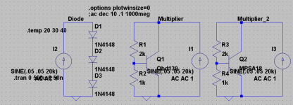
The multiplier has multiple RC thingies, not so clean as a diode string. Maybe we should simulate.
- keantoken
The multiplier has multiple RC thingies, not so clean as a diode string. Maybe we should simulate.
- keantoken
Member
Joined 2009
Paid Member
Maybe we should simulate.
In this team, you are the guy for this - it's an interesting question as to the differences, a much wider topic than the headamp and quite possibly will draw some further attention from others who haven't previously given this thought.
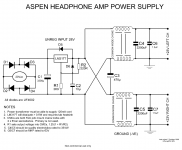
The psu design is great. Honestly. Pulling the regulator back by the rectifiers puts all the non-linear elements together and far away from the amp. The amp 'sees' caps and coils. Sometimes you don't know it's the right solution whilst toiling away, but I often get that feeling when something just seems to slot into place with ease and this one is it.
p.s. I like Vbe multipliers.
Kean,
I'm sorry about the fun..... an intellectual exercise is sure fun, but it's not something everyone building the project will share!
Yeah, do please simulate, see what happens, I'm off for a latte in my favorite cafe - bifurcating the subjective is a hobby of mine......
Hugh
I'm sorry about the fun..... an intellectual exercise is sure fun, but it's not something everyone building the project will share!
Yeah, do please simulate, see what happens, I'm off for a latte in my favorite cafe - bifurcating the subjective is a hobby of mine......
Hugh
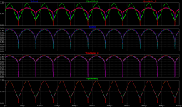
Look, doesn't the diode have a better curve?
Of course, a BD139 isn't going to make a good multiplier anyways, because of it's small current gain. The base current causes error in the divider. We've switched to an MPSA18, now look how nice that is? I guess I have very good intuition, I should stop ignoring it. CFP Vbe multiplier, anyone? 😉
The diodes also have less phase shift.
So YES, if you were using a fat, low-gain transistor for the Vbe multiplier (which is pretty much always) then there was some difference. I vote that if we use a multiplier, we use a high-gain transistor to best approximate the diode curve. (but the diodes still take the cake, for having that perfect spherical curve... 😉)
I also ran a temperature simulation, and you can see that the MPSA18 multiplier beats the BD139 in that regard too.
(Bigun, I know you meant it in the best sort of humor but that can confuse people in the worst way...)
I'm not opposed to having fun, and this has been fun for me.
- keantoken
Attachments
Last edited:
I vote that if we use a multiplier, we use a high-gain transistor to best approximate the diode curve. (but the diodes still take the cake, for having that perfect spherical curve... 😉)
FWIW I have been using the 2SA1381 as vbe - hfe=~300.
Sounds fine to me!
😉
Member
Joined 2009
Paid Member
(Bigun, I know you meant it in the best sort of humor but that can confuse people in the worst way...)
sorry, I wasn't trying to make any fun of this, I was poking fun at Hugh but I meant exactly what I said with regards my respect for you use of Spice and your insights into the Vbe multiplier workings. I'm a bit lazy, I simply view the Vbe multiplier as a drop in 'module' that works and that's about it. I use the BD139 for this purpose, never crossed my mind that there might be a better choice. I also like to run simulations - much more so than Hugh, I find it a good learning exercise and more relaxing than building things (lots of opportunities for frustration when you try to build things). I've been playing with the Zen amp for the past few weeks, multiple simulations and a prominent Cap Multiplier !!!
Anyhow, forums are as bad as email at communicating intent/body language etc., but we're getting better at it.
- Home
- More Vendors...
- AKSA
- Aspen Headphone Amp