Hehe...
The Russians beat me to it😉.
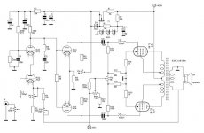
My idea to use a 6sn7 Cascode as an input stage has (of course) been done before. I always Google in different languages to find new things and voila [img1].
After playing some more with the sim in my previous post I ended up with values close to the one in this schematic (before I found it).
I will be taking this route: Cascode + long-tailed pair phase splitter + UL output
Again, thanks for all the help and brainstorming.
P.S. the schematic is missing a 1uF cap in the phase splitter but this was explained in the text.
The Russians beat me to it😉.
My idea to use a 6sn7 Cascode as an input stage has (of course) been done before. I always Google in different languages to find new things and voila [img1].
After playing some more with the sim in my previous post I ended up with values close to the one in this schematic (before I found it).
I will be taking this route: Cascode + long-tailed pair phase splitter + UL output
Again, thanks for all the help and brainstorming.
P.S. the schematic is missing a 1uF cap in the phase splitter but this was explained in the text.
Attachments
Last edited:
Are those 100uH inductors in the EL84 grids low Q (such as some beads are)?
With Push Pull outputs, Reactances in two Plates, two g2 Screens, and also two g1 Grids makes me nervous.
A lot of those reactances depends on the leakage reactances of all the primary windings to each other (Plate, UL tap, UL tap, Plate).
Build an amplifier, end up with an oscillator.
Build an oscillator, end up with an amplifier.
Sometimes that happens.
Missing 1uF?
Did you mean from R6, 1 Meg Ohm, a 1uF bypass cap to ground?
I did not see where you found the text that explained that.
Last edited:
Are those 100uH inductors in the EL84 grids low Q (such as some beads are)?
With Push Pull outputs, Reactances in two Plates, two g2 Screens, and also two g1 Grids makes me nervous.
A lot of those reactances depends on the leakage reactances of all the primary windings to each other (Plate, UL tap, UL tap, Plate).
Build an amplifier, end up with an oscillator.
Build an oscillator, end up with an amplifier.
Sometimes that happens.
Missing 1uF?
Did you mean from R6, 1 Meg Ohm, a 1uF bypass cap to ground?
I did not see where you found the text that explained that.
Indeed the 1uF cap to ground is missing and this was explained (in Russian) on the original site. I will be placing grid-stoppers instead of the small coils in my final design. This schematic is for reference only, I will post my final schematic later.
Good on you: the 6L6-oids can sound very good indeed.Hello to all reading this,
I would like some guidance on the design decisions that follow in my 6l6 amplifier build:
Two years ago I decided that I would like to build two Monoblock 6l6 based amplifiers. At the time (with a certain budget restrain) I ordered components that would allow me to build "Williamson" Ultra Linear style amplifiers with bias points slightly adjusted for a somewhat lower supply voltage. I completed two chassis, each with a power supply transformer, OPT and 5 tube sockets installed.
Don't worry about it. You don't need huge amounts of gNFB for sonic excellence. All that's required is to add enough to take the edge off. I used Hammond OPTs for a 6L6-oid design that used 807s instead. With parallel lNFB (~7.0dbv) and some 13 dbv gNFB, no problems with stability, and none of that lifelessness that excessive amounts of gNFB can cause. Hollow state starts out a good deal more linear than solid state, so doesn't require as much correction. Even when it was running way too much gNFB, there was no stability problems.Then came the quite naïve realization (after carefully reading many articles on the Williamson amplifier) that my choice of output transformer might become a severe design limitation. At the time (again due to budget limitations) I chose the Hammond 1620 output transformer. My reasoning was that the 20 Watt power limitation was not going to be too big of a deal as my B+ supply voltage was going to be somewhat lower anyway (and thus the resulting output power).
The first schemo IMG1.PNG) looks to be the best one. The second one and that "Einstein amp" both suck. The low frequency cutoffs aren't staggered, and that's asking for trouble right there. As for that first schemo, not a big fan of Ultralinear, and definitely ditch the CCSs in the tails of the finals. You're better off using fixed bias instead. Even cathode bias is better than that.
Jeez, let's all jump on the 'Einstein amp' and its poorly chosen poles --
I didn't offer it up as a finished design. Actually, I meant the farthest thing from that. It's an example of the Williamson topology used with triode output tubes and without global NFB.
The RC time constants are *easily* changed simply by changing the values of the coupling capacitors. I assumed we're all capable of figuring that out. Choose those RC values carefully to stay away from the poles introduced by the output transformers, use no more than 6dB of gNFB to 'take the edge off', and there are no stability problems.
So yes, I agree that as is, that 'Einstein amp' sucks. But it's a reasonable place to *start* for a PP class A triode amp.
Pretty funny how everyone seized on the poles all being the same in that design and missed the intended point completely. Ah, the innerwebs...
--
Also, I believe there is a mistake in that Einstein amp (which comes from John Broskie's site, incidentally). I have no idea if the 1uF cap going from the cathodyne grid leak resistor to ground is supposed to be there. I've never seen a cap used that way in any other design that uses a concertina/cathodyne/split-load. Perhaps I'm missing its purpose, or perhaps it's a simple mistake.
Last edited: