Yes, they have done a great job archiving all those magazines, a treasure chest full of great information.Some time ago, a member discovered this valuable website. I think you will find all the articles you need and much more!
Documenting the History of Radio TV and FM broadcasting
Finally, I had chance to read the 1948 March article, it is interesting to note that despite the title that featured the 6AS7G, the "hardest working tube" was actually the 6N7 driver. The amplifier also used a lot of feedback (27 dB) from the output of the driver to the input tube's cathode, the rather high amount of feedback could be used beacuse the feedback signal did not have to go through the two transformers in the circuit, so the amplifier was completely stable.
OTOH, since the feedback was not global, the output impedance of the amplifier was quite high, so the damping factor was rather low (~2), perhaps it was fine with loudspeakers made back in the day, but not so good if you plan to use the amp with some modern speakers.
OTOH, since the feedback was not global, the output impedance of the amplifier was quite high, so the damping factor was rather low (~2), perhaps it was fine with loudspeakers made back in the day, but not so good if you plan to use the amp with some modern speakers.
In my opinion the construction presented in RCA Ham Tips September-October 1948 is the most advanced design of all these we have now seen here.
That design is the only that uses vacuum tube (6SN7) driver stage instead of interstage transformer and takes advantage of the distortion cancelling of that driver stage.
That design is the only that uses vacuum tube (6SN7) driver stage instead of interstage transformer and takes advantage of the distortion cancelling of that driver stage.
Member
Joined 2009
Paid Member
I was going to ask the same question- these devices burn a lot of power in Rk too (I have a SE amplifier based on this tube and Rk gets pretty hot).
Artosalo, why is it, that you're not using fixed-bias for the 6AS7's ?
I simply rely on the application suggestions of RCA.
With fixed bias the thermal run-away is likely to happen.
See 2. line at "Application Consideration".
Attachments
Last edited:
I certainly understand what RCA is saying but,...
That will probably hold for the tube when used in circuits it was originally designed for, i.e. Horiz. Output Amplifier and PSU Series Regulator Services.
At least Philips and US Mil-spec's are open to Fixed Bias.
That will probably hold for the tube when used in circuits it was originally designed for, i.e. Horiz. Output Amplifier and PSU Series Regulator Services.
At least Philips and US Mil-spec's are open to Fixed Bias.
Attachments
Philips seems to accept fixed bias, but suggests auto bias.
With fixed bias a separate anode resistor dropping min. 15 V must be used. Rg max. is 100 k with fixed bias, 1 M with auto bias.
6AS7-G PP amplifier needs some 220...240 Vpp grid voltage at full power.
To generate this voltage with vacuum tube driver requires +Ub not less than 350 V.
Although 250 V +Ub is sufficient for fixed biased output stage, the driver still need much higher supply voltage.
This makes the power supply a bit complicated.
With auto bias a single 375 V power supply is sufficient and 125 V can be "lost" in cathode resistors without big trouble.
Last edited:
Hi,
Just for info, my apologies if I sent some of you on the wrong track.
I should have mentioned the Lilliput amplifier by Mega Herz, not the Triodino.
Both are SE amps but Mega Herz also has a PP 6AS7 .
http://www.diyaudio.com/forums/tubes-valves/43182-lilliput-amp-2.html
Cheers, 😉
Just for info, my apologies if I sent some of you on the wrong track.
I should have mentioned the Lilliput amplifier by Mega Herz, not the Triodino.
Both are SE amps but Mega Herz also has a PP 6AS7 .
http://www.diyaudio.com/forums/tubes-valves/43182-lilliput-amp-2.html
Cheers, 😉
With fixed bias a separate anode resistor dropping min. 15 V must be used.
I think this suggestion has to do with equalizing the anode-loads as well as the suggested cathode resistor dropping at least 7,5V in combined fixed/auto bias.
All very well when used for a series regulator in a power supply.
I fail to see why this is could useful in a PP audio circuit and protect the tube from thermal run-away.
Obviously driving a 100K grid resistor will put a higher demand on the driver compaired with the 1M suggested for auto-bias.
You're right about the simpler power-supply circuit f.u.w. auto-bias even if a simple voltage doubler should take care of the needed higher supply voltage for the driver.
I suppose it's time to heat the soldering iron to settle this 🙂
Anyone ...?
Hi,
Always keep in mind that these 6AS7G's and relatives are dual triodes, NOT twin triodes.
So individual bias adjustment is mandatory or else it'll take an awful lot of matching which IME is useless anyway.
Cheers, 😉
Always keep in mind that these 6AS7G's and relatives are dual triodes, NOT twin triodes.
So individual bias adjustment is mandatory or else it'll take an awful lot of matching which IME is useless anyway.
Cheers, 😉
Member
Joined 2009
Paid Member
I should have mentioned the Lilliput amplifier
That was the basis for my first tube amp project 🙂
http://www.diyaudio.com/forums/tubes-valves/167872-my-cellini-triode-amp.html
I have thought about this 6AS7 tube a few times since and I am always uncomfortable with the inefficiency of burning so much heat in the cathode resistor. It's a high current tube with a high grid voltage - a bit of a bad combination really. There seems to be many better choices of output power tube than this one. The low Rp is nice, but if you're not going OTL (for which sand is a better choice in my view) and you have an output transformer this benefit is less obvious because a tube with higher Rp will use a larger winding ratio for more or less the same damping factor at the speaker.
Perhaps I'd be happier using it with fixed bias and a fuse in the supply line !
McProud 6AS7G monoblock clone:
An externally hosted image should be here but it was not working when we last tested it.
I have the original article if you still need it...
I won't be able to get to it till Dec 19th when I return home...
I won't be able to get to it till Dec 19th when I return home...
This is maybe a bit off topic, but because here was last discussed about 6AS7G PP amplifier, I decides to continue here too.
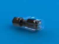
I manage to get custom made 5k to 8/4 ohms toroidal OPTs for 6AS7G PP amplifier from Toroidy (Poland). The size of this OPt is considerable, some 105 mm x 65 mm.
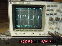
I am very satisfied about the test results. Most of the measurements I have done with 6 dB GNFB, but I also measured the frequency response with no GNFB.
Also the attached 10 kHz square wave plot was taken with no GNFB.
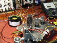
Attached are also the schematic of my old 6AS7G prototype, the photo of the used test setup and test results.
I manage to get custom made 5k to 8/4 ohms toroidal OPTs for 6AS7G PP amplifier from Toroidy (Poland). The size of this OPt is considerable, some 105 mm x 65 mm.
I am very satisfied about the test results. Most of the measurements I have done with 6 dB GNFB, but I also measured the frequency response with no GNFB.
Also the attached 10 kHz square wave plot was taken with no GNFB.
Attached are also the schematic of my old 6AS7G prototype, the photo of the used test setup and test results.
Attachments
- Status
- Not open for further replies.
- Home
- Amplifiers
- Tubes / Valves
- Article Wanted - "High Quality Amplifier with the 6AS7G" by McProud