Just started stuffing Georj's boards - he was always so kind and helpful. I particularly enjoyed our email exchanges - he will be missed.
Nelson, in the VFET article, states that input impedance should be around 100 or so ohms to obtain good bandwidth. My preamp has output impedance of 150 ohms SE or 1000 ohms balanced.
Am I limited to SE?
Also in the CSX1 schematic there is a 8 ohm resistor from output to ground that was not in the original circuit. What is its function or more to the point is it necessary?
Thanks
Bob
It's function is a speaker load. More to the point, your going to need it!...Also in the CSX1 schematic there is a 8 ohm resistor from output to ground that was not in the original circuit. What is its function or more to the point is it necessary?
Thanks
Bob
I am very sorry to tell you that my friend permaneder died suddenly on the 12th of August…….
R.I.P Georg
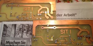
Memory of Georg Meisenbach aka Permaneder.
Last time i have ask afford his Sit CCS pcb´s and
this gentleman send me old hand made prototypes generously.
Thanks my diy friend Georg wish Father and Mother of All Forms of Life
keep Your Soul in His Heart. Condoleances for family.
Requiescat in pace
Rest in Peace


Attachments
Could be a Zobel net? Dear Generg?
Sorry for the question for beginners in this time
Deep regards, one day we talk here... Better is talk with people of similar tastes. How many questions we left without answers simply because we never asked.
Probably now we are encouraging to not give the quesion answered when actually wasn't.
Sorry for the question for beginners in this time
Deep regards, one day we talk here... Better is talk with people of similar tastes. How many questions we left without answers simply because we never asked.
Probably now we are encouraging to not give the quesion answered when actually wasn't.
Sadly, it was Permender who passed. He was running the Group Buy for boards for this amp. He was on the second round. I was lucky enough to get mine from the first.
Anyone over there know the status of the second round? Had he completed the order? Or is it just a list still?
Anyone over there know the status of the second round? Had he completed the order? Or is it just a list still?
Hi Bravi
???????
Happyly he is alive !
Long life Generg
THX soundhappy, I did not want to answer because I just rested in peace......🙂
Apologies to all for the mix up.
All count is good intention not mistake 🙂
Taken from another thread this looks like a good candidate for the VFETs power supply PCB?
Amplifier Power Supply PCB | Chipamp Electronics
Regards,
Dan 🙂
Amplifier Power Supply PCB | Chipamp Electronics
Regards,
Dan 🙂
I am very sorry to tell you that my friend permaneder died suddenly on the 12th of August…….
R.I.P Georg
I'm sorry to hear that. He was a great guy, helped me alot too - especially getting started and understanding the basics with my F6 build. God' speed, Georg.
Am I on the right track here where you run wires from the IRF's regulated supply, to supply the bias supply?
Regards,
Dan 😱
An externally hosted image should be here but it was not working when we last tested it.
Regards,
Dan 😱
I have yet to build mine, as I am still doing a DDDAC. I have gathered most of the parts (chassis excepted).
I think the 2 positions marked "+reg" and "-reg" are measuring points for setting the voltage using the 2 adjustable resistors. Unlike the main power, the bias power comes straight out of the rectifiers, and is regulated, and adjusted, on the main board. So the +/- wires from the small transformer/rectifiers to to -15/+15, one on each side of the board. Where as the main power is both rectified, and has the large cap bank outboard. Main power comes in through the "+/- 32V" connectors, and has common "GND" at the bottome there. These double holes, with the white line connecting them indicates a position for a blade connector to go, or a loop of wire to hook your multimeter to.
Note : I could be wrong, and will not be offended if someone points it out.
It won't hurt my feelings if someone puts together a "how to" use Permender's boards. I think I can follow the Nelson Pass schematics well enough, but it did take some thinking to figure out where the 2 power supplies per channel are housed.
Permaneder did say,
Sounds like I might need some of these,
3FD-312 Tamura | MT2102-ND | DigiKey
And some of these,
2W005G-E4/51 Vishay Semiconductor Diodes Division | 2W005G-E4/51GI-ND | DigiKey
Regards,
Dan 😕
Small auxiliary boards for the BIAS supply transformers and their rectifiers will follow soon.
Sounds like I might need some of these,
3FD-312 Tamura | MT2102-ND | DigiKey
And some of these,
2W005G-E4/51 Vishay Semiconductor Diodes Division | 2W005G-E4/51GI-ND | DigiKey
Regards,
Dan 😕
Am I on the right track here where you run wires from the IRF's regulated supply, to supply the bias supply?
An externally hosted image should be here but it was not working when we last tested it.
Regards,
Dan 😱
NO! You can't do that.... bias power supply most be 'floating' so separate. And the bias must be present before the Vds, the 24V, is applied. Otherwise you destroy the VFETs.... Use the bias supply suggested by Nelson Pass....
NO! You can't do that.... bias power supply most be 'floating' so separate. And the bias must be present before the Vds, the 24V, is applied. Otherwise you destroy the VFETs.... Use the bias supply suggested by Nelson Pass....
Thanks Walter,
A slight misstep on my part. As you can see from my post I'll be buying some small transformers and bridge rectifiers for the +/-15.
Regards,
Dan 🙂
- Status
- Not open for further replies.
- Home
- Amplifiers
- Pass Labs
- Article - Sony VFETs part 1