And your actual gate time in ms is ? Microphone distance ?
Simon,
I believe gate time was about 4.5ms.
Mic was about 800mm from the baffle, 1150mm from the nearest boundary (i.e., ceiling).
EDIT: attached a measurement from this morning along with a picture from my setup. Speaker baffle is about 1000mm from back wall. Mic is about 1200mm from the ground and 1150 from the ceiling and 787mm from speaker baffle.
Attachments


Last edited:
This is probably due to signal to noise ratio in low frequencies. Don't know how loud was your excitation signal, but worth a try to make speaker play louder. Also sine sweep will be more immune to SNR at same level compared to MLS ... again don't know what type of test signal did you use.
All in all - it is to be expected that with 4.5ms you will not get a clean signal down low. Check into near field measurements and merging the near field to far field later. See VituixCAD instructions for step by step instructions.
PS. Also making the sweep longer (16k -> 32k ->64k) will help get better SNR for low end...
Last edited:
This is probably due to signal to noise ratio in low frequencies. Don't know how loud was your excitation signal, but worth a try to make speaker play louder. Also sine sweep will be more immune to SNR at same level compared to MLS ... again don't know what type of test signal did you use.
All in all - it is to be expected that with 4.5ms you will not get a clean signal down low. Check into near field measurements and merging the near field to far field later. See VituixCAD instructions for step by step instructions.
PS. Also making the sweep longer (16k -> 32k ->64k) will help get better SNR for low end...
Thanks Ergo,
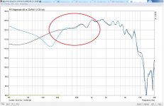
Unfortunately, the issue continued with using longer sweeps. I've not had the same issue with REW or HolmImpulse - but I still want to stick to ARTA because its integrates so well with VituixCAD. I've read through VituixCAD's measurement preparation document and learned about merging far-field with near-field. However, with near 4.5ms of gating time, I was hoping far-field measurements would be accurate in the 300hz - 600hz range. Unfortunately, I'm having as much as 1db-3db variance in that region, which I think can drastically impact the level (SPL) at which I merge far-field with near-field --> which I'm concerned can further impact the tonal balance of the speaker (e.g., too much or too little bass).
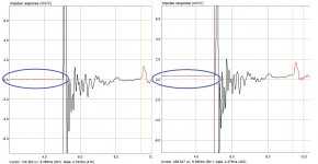
One thing I'm curious about is why, when making consecutive measurements, sometimes the impulse response starts a level zero, and some times slightly above/below it. It seems to correlate with how the FR is then derived (with more wave-ness when the IM response is not starting at level zero). See attached images - I'm really not explaining it well.
Attachments
Thanks Ergo,
<<<SNIP>>>>
One thing I'm curious about is why, when making consecutive measurements, sometimes the impulse response starts a level zero, and some times slightly above/below it. It seems to correlate with how the FR is then derived (with more wave-ness when the IM response is not starting at level zero). See attached images - I'm really not explaining it well.
Dhar,
That looks like some sort of DC-offset or maybe just a simple ground-loop ( measured against a reference channel while in 2-channel mode > though I don't really know which ).
Hopefully it's not a dc off-set caused by your sound card starting to fail.
Are you able to move your measurement setup to a laptop ( running on batteries ) ?
If so ( & the problem goes away, it's a ground-loop ) you'll want to continue in that battery mode or get a high quality Iso-Transformer ( to put on the output of the sound-card ) or find some other way to break up ( what's quite likely a ground-loop ).
🙂
Last edited:
Earl,
Thanks for responding. I'll definitely try that this evening. I'm using Focusrite Scarlette Solo as my pre-amp, which is powered via its USB connection to my desktop. The Focusrite is then connected to a Dayton Audio APA150 amplifier.
I'll try working off a laptop (powered via batter), but if the problem still persists, do you think I should try a cheater plug (i.e., no ground) on the amplifier?
Or do you think whatever issue I'm having with the DC-Offset, its happening at the pre-amp level?
Hi DKalsi,
there could be several sources of error that manifest as subsonic (alost DC) shift:
1) air conditioning changes sound velocity and generate noise in subsonic region.
2) impulsive noise can contaminate swept sine measurement more than PN Pink noise (try make measurement with both)
3) when using swept sine the measurement duration is double the value of swept duration, so be quiet until measurement stops.
4) loudspeaker can exhibit large hysteresis distortion, so try to give loudspeaker burn in time.
5) there can be changes in connector resistance during measurements (typical for on-board cheap connectors).
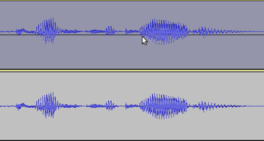
6) clipping of signal is also generator of subsonic noise (check time record of signal??)
7) some sound cards (like Scarlett or Behringer) has bad channel separation which can contaminate dual channel measurement (so give try to single channel measurement??)
8) some soundcards has very high distortions on low frequencies (like Steinberg UR22).
9) battery operated microphones, ground loops, and more...
try to eliminate all this????
Ivo
there could be several sources of error that manifest as subsonic (alost DC) shift:
1) air conditioning changes sound velocity and generate noise in subsonic region.
2) impulsive noise can contaminate swept sine measurement more than PN Pink noise (try make measurement with both)
3) when using swept sine the measurement duration is double the value of swept duration, so be quiet until measurement stops.
4) loudspeaker can exhibit large hysteresis distortion, so try to give loudspeaker burn in time.
5) there can be changes in connector resistance during measurements (typical for on-board cheap connectors).
6) clipping of signal is also generator of subsonic noise (check time record of signal??)
7) some sound cards (like Scarlett or Behringer) has bad channel separation which can contaminate dual channel measurement (so give try to single channel measurement??)
8) some soundcards has very high distortions on low frequencies (like Steinberg UR22).
9) battery operated microphones, ground loops, and more...
try to eliminate all this????
Ivo
Back in post #581 I had a similar experience with a DC offset in the impulse measurement that randomly varied every time a measurement was taken:This is probably due to signal to noise ratio in low frequencies. Don't know how loud was your excitation signal, but worth a try to make speaker play louder. Also sine sweep will be more immune to SNR at same level compared to MLS ... again don't know what type of test signal did you use.
https://www.diyaudio.com/forums/multi-way/76977-arta-12.html#post5232776
This was with a dual channel measurement. In that case the root cause of the problem seems to have been insufficient signal level or signal to noise ratio at low frequencies on the reference input. (2nd channel)
The reason for this is that I was trying to measure a ribbon tweeter that was being driven through a 2nd order 3Khz high pass filter (for protection from low frequencies) and connecting the 2nd reference channel after the high pass filter (across the driver) to cancel out the high pass filter effects on the measurement.
However this only works to about 40dB down from peak signal level before random errors in the impulse DC offset start to show up. In dual channel mode there seem to be significant inaccuracies if the reference channel level drops too low especially at low frequencies. I'm not sure if this is a bug or just a fundamental limitation that can't be avoided.
So if using dual channel mode I would check that the reference channel input level is sufficiently high - ideally the microphone input on the Left Chanel and reference signal on the Right channel should be a similar amplitude to each other as reported on the bar graph in the capture window.
Or try single channel measurement mode.
I believe gate time was about 4.5ms.
Mic was about 800mm from the baffle, 1150mm from the nearest boundary (i.e., ceiling).
Indeed. With a 4.5ms gate time you will only get useful measurements down to approx 300Hz, anything below that is going to be inaccurate and may be inconsistent from one measurement to another.All in all - it is to be expected that with 4.5ms you will not get a clean signal down low.
Another thing I notice is in the impulse response image in post #682 the start marker is awfully close to the start of the impulse. In single channel measurements with some sound cards there can be a small random differences in signal propagation delay through the sound card drivers from one measurement to another.
This causes the reference point for the start and end markers to move around slightly each time you take a measurement. If the start marker is too close to the beginning of the impulse and the delay on one measurement pushes the marker too close to the impulse you can end up truncating part of the beginning of the impulse, depending on what windowing method you have selected.
While this won't be the cause of the DC offset in the impulse it can add significant errors in the frequency response. There are a few things you can do to avoid this.
1) If the sound card is doing this, find a better sound card. Better quality cards don't have this issue with random sample processing delays each time the device is opened.
2) Use dual channel mode - in dual channel mode the extra random delay will be the same in left and right channels and will cancel out. Dual channel mode ensures absolute consistency in timing from one measurement to another which cannot be guaranteed in single channel mode.
3) Back the cursor off a bit. I always put the start cursor significantly further before the beginning of the impulse than you show here. There should be silence before the start of the impulse so going a little bit too far before the impulse should not affect the response so it's better to have the start cursor a bit too far to the left than too close to the impulse.
I would also bring that end cursor slightly to the left. Depending on what windowing algorithm you have selected, that cursor is too close to that obvious reflection (the downwards dip) so some of the reflection will be included in the measurement especially if there are timing variations from one measurement to another.
If you have made good choices for start and end cursors you should be able to move them around a little without any significant change in the response, and this is one way that I check I have them well positioned.
Last edited:
Hi Simon,
thank you for adding dual channel reference channel problem.
It is especially important when using swept sine. As a rule of thumb - it is advisible to retain at least 14 bit of precision for high quality measurements (swept sine peak level above -12dB FS).
Ivo
thank you for adding dual channel reference channel problem.
It is especially important when using swept sine. As a rule of thumb - it is advisible to retain at least 14 bit of precision for high quality measurements (swept sine peak level above -12dB FS).
Ivo
Would it make sense to add a detrend function in ARTA to remove any DC and linear trend in an impulse response? This would allow removing most of the subsonic noise from the impulse response, no matter what the cause might be (and it sometimes is hard to avoid it).
Would it make sense to add a detrend function in ARTA to remove any DC and linear trend in an impulse response? This would allow removing most of the subsonic noise from the impulse response, no matter what the cause might be (and it sometimes is hard to avoid it).
It will not help, as this is not kind of DC offset distortion, it is a very low frequency distortion problem.
Ivo
It will not help, as this is not kind of DC offset distortion, it is a very low frequency distortion problem.
Ivo
It does help, I often do it with MATAA before FFT of the impulse response. The relevant frequeny components are so low that the FFT has no way of discerning it from DC. Removing any DC or linear trend takes away most of the problematic low-frequency content that is not resolved in the impulse response.
Is a constant DC offset in an impulse response from a microphone (which is inherently AC coupled, acoustically) ever a valid thing or can it only ever be an artefact of a measurement or processing error ?It will not help, as this is not kind of DC offset distortion, it is a very low frequency distortion problem.
Ivo
I would assume that in real, valid microphone measurements that there should never be a DC offset in an impulse response since that would imply signal content at 0Hz, not possible from a microphone ? So the processing algorithm is inferring content at 0Hz that doesn't exist ?
When I was having this issue with impulse response DC offset, every time I took a measurement I was getting a different random DC offset (presumably due to low signal to noise ratio at low frequencies on the 2nd reference channel input due to the high pass filter in front of both speaker and reference channel input) and the result was that the impulse response was absolutely identical every time except for a different DC offset.
This DC offset however would cause severe changes in the low frequency response from one measurement to another - even worse than what Dkalsi shows. Occasionally, by luck, I would capture an impulse with zero DC offset and the frequency response produced was valid and free of any obvious defects within the valid time/frequency uncertainty window.
So it seems to me if the DC offset as displayed in the lead up to the impulse start could be cancelled out either automatically or manually that it would help to get valid measurements in conditions where this may be an issue, however I didn't see any way in the impulse viewing window to alter the DC offset of the impulse manually.
Are you sure such (optional ?) DC offset removal in the impulse response window couldn't be beneficial in some circumstances if the impulse is otherwise valid except for the offset ? (which seems to be the case in the situation I had)
Last edited:
I would assume that in real, valid microphone measurements that there should never be a DC offset in an impulse response since that would imply signal content at 0Hz, not possible from a microphone ? So the processing algorithm is inferring content at 0Hz that doesn't exist?
It's not the processing algorithm to blame. It's rather the low frequency noise introduced to the measurement (acoustically/ambient low-frequency noise, or imperfections in the electronics in the measurement chain). However, your point remains the same. It would be useful to remove DC and very-low frequency components from an impulse response to deal with such issues. 🙂
I'm not sure that there isn't some blame in the dual channel algorithm in ARTA though. The reference channel was sampling at 192Khz, 24 bit, and is measuring an electrical signal from the speaker terminals, not a noisy acoustic signal. Noise levels should be very low.It's not the processing algorithm to blame. It's rather the low frequency noise introduced to the measurement (acoustically/ambient low-frequency noise, or imperfections in the electronics in the measurement chain).
And yet when there was more than about 30dB of variation in amplitude in the reference channel (high pass function) there were severe errors being introduced in the low frequency response, (due to the DC offset in the resulting impulse response) that did not occur in single channel mode. And that offset error was randomly different with every measurement taken.
With 24 bits available -30dB is still about 19 bits of resolution, so signal to noise ratio should still in theory be good.
What I also found is that the absolute level of the reference signal was not the issue - if I had a near flat reference signal (for example the direct output of the test amplifier) I could reduce it's amplitude down to -60dB or more and the resulting impulse response is still perfectly OK with no DC offset.
It's only when the reference channel has large frequency response variations that exceed about 30dB from one frequency range to another that there is an issue. This makes me wonder if there is a bug in the algorithm and it has not be tested with a reference channel input that is extremely non-flat in response.
This may be an expectation error on my part - I initially assumed that as well as providing time correction dual channel mode should act as a sort of "difference" function, where errors in the primary signal can be subtracted by the reference channel.
So for example if you measure the acoustic response of a speaker in dual channel mode, connecting the reference channel directly to the speaker terminals precisely cancels any frequency response errors that are introduced by the test amplifier and even the resistance of the speaker cable.
And this is true - but apparently only if the deviations in response in the reference channel are small. Large deviations like 30dB cannot be subtracted from the measurement without introducing DC offset in the impulse response and subsequent errors at low frequencies.
Is this a bug, or is this an incorrect expectation from me about what the dual channel mode can achieve in terms of cancelling frequency response errors of the test signal presented to a driver ? I have not performed similar testing with other software besides ARTA.
Last edited:
you can also have a look at SATlive SATlive Audio Measurement Software - perhaps it would help - read the manual for yur topic
Simon,
all that you said is written in manual, and it is characteristics of dual channel Fourier analysers, known for fifty years.
I will repeat recommendation from manual:
For dual channel analysis you have to use sound cards with good low-frequency response, but for many cheap sound cards that have restricted low frequency response /excitation it is better to use single channel system. That is why I implemented both methods.
Ivo
.... For dual channel analysis you have to use sound cards with good low-frequency response, but for many cheap sound cards that have restricted low frequency response /excitation it is better to use single channel system. That is why I implemented both methods.
Ivo
Thanks Ivo.
I switched in an old M-Audio MobilePre USB for my Scarlette Solo (gen2) and achieved better results. Still not quite 0 DC offset, but better for sure.
Is there a specific unit that you recommend that you have had good experience with?
Thanks,
D
Still troubleshooting....
Wanted to know if it means anything that I experience no DC offset when measuring using MLS but continue experiencing DC offset issue when measuring using Sweep
Wanted to know if it means anything that I experience no DC offset when measuring using MLS but continue experiencing DC offset issue when measuring using Sweep
Also -
I get near 0 (almost none whatsoever) DC Offset when I use "single-channel" mode.
Changing mics didn't help any.
Moving to a dedicated HT power outlet (straight from the power panel to the one single home theater outlet) didn't help any.
Working off of a laptop didn't help any.
The only things that helped so far are:
1) Using MLS instead of Sweep
2) Moving to single-channel mode
3) Using an older mic preamp (small change, but an improvement nonetheless).
Perhaps I need a better mic preamp? Suggestions anyone?