gdan, it is important to measure with high frequency resolution meaning longer time windows and in a space that's as much as possible free from room resonances. Noteworthy resonances can be visible as bumps in spatially averaged measurements plots. I'd increase the listening window to 30 deg horizontally, if I were you.
yes, I know, but this is not possible to do it in a living room.
The listening window was only 10 degrees because I was trying to set the level of the tweeter relative to the midwoofer in my active system and I was wandering if it is better to do it by measuring not only on axis but on a listening window.
Anyway my question was mainly about how the "power average" is calculated by ARTA.
Thanks to Ivo for his answer.
I had struggled many times to get my measurement setup with ARTA to show accurate SPL also when I use 2 channel measurement. It was ok with 1 channel but enabling the 2ch it threw it off by tens of dB.
I did finally achieve a reasonably good match with CLIO FW (within 2dB) during this weekend. I did write down the instructions for my own use but perhaps these will help others too.
https://1drv.ms/b/s!AvVPh3wl37NzgZlccw7NGQBiEvjw6g
Ivo, if there is room for future requests then perhaps the "gain" fields in ARTA setup could also have a drop down selection between the absolute gain vs dB gain. This way there would be less calculations needed as the knows gains for amp or attenuator etc are usually in positive or negative dB respectively.
Does anyone know if ARTA can save the frequency data? On the website, it says that in demo mode, data cannot be saved.
Thanks,
-Andy
Thanks,
-Andy
Yes, even the free version can export frequency response data. If you want that to be SPL and phase, you need to have both showing in the frequency response plot window. One of the menus in that window controls what is shown.Does anyone know if ARTA can save the frequency data? On the website, it says that in demo mode, data cannot be saved.
Thanks,
-Andy
The free version cannot save the IMPULSE (time domain) data.
Hi Ivo,
You may have answered this question before, but this is my present problem:

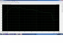
I tried different microphones, measured different tweeters, even tried different sound cards. The three 'chimneys' always appear at the high frequency end of the graph. In STEPS, they are not there.
Can you please help me out? Thanks ahead.
You may have answered this question before, but this is my present problem:
I tried different microphones, measured different tweeters, even tried different sound cards. The three 'chimneys' always appear at the high frequency end of the graph. In STEPS, they are not there.
Can you please help me out? Thanks ahead.
Please try callback measurement off soundcard IR. Then send me both pir files.
It looks like some kind of pulsive interference exist.
Ivo
It looks like some kind of pulsive interference exist.
Ivo
Swept sine distortion estimation problem
Hi Paul,
After our email conversation, here is explanation for other Forum members.
Calculation of distortions from swept sine response using Farina method is very popular, and almost all computer based measurement systems are offering it. I must say that this method is not ideal and I have written in manual that program STEPS offers more reliable method for measuring distortions.
The problems can arise on both side of spectrum, on very low and very high frequencies. In your case we have problem at high frequencies. You have used anti-aliasing filter that has very large cut-off slope with very high drop in group delay at 24-25kHz, although you use sampling frequency of 96 kHz.
Large group delay at 24-25 kHz makes time shift of swept sine parts, and we get time smearing and overlapping of distortion induced components that normally appears before the linear part of impulse response (you can clearly see second harmonic at 24.5/2 kHz, third harmonic at 24.5/3 kHz, etc.).
Generally, to minimize this effect we have to use an anti-aliasing filter that has cut-off frequency close to the half of the sampling frequency, with reasonably large change in group delay. Normally we have this situation with all sound cards, but not always, i.e. If you use WDM driver and Control panel sound control has different sampling frequency then set in ARTA, Windows does sampling rate conversion and steep filtering.
Best,
Ivo
Ivo,
You have been a great help and thank you for your explanation. It is good to know what is going on under the hood.
The ARTA license was my best software purchase ever.
Keep up the good work,
Paul
You have been a great help and thank you for your explanation. It is good to know what is going on under the hood.
The ARTA license was my best software purchase ever.
Keep up the good work,
Paul
Hi Ivo,
You may have answered this question before, but this is my present problem:
View attachment 612187
I tried different microphones, measured different tweeters, even tried different sound cards. The three 'chimneys' always appear at the high frequency end of the graph. In STEPS, they are not there.
Can you please help me out? Thanks ahead.
I got these strange THD bumps in upper mid- and range, too, even with ASIO drivers. They went away after clean setup of Windows.
Unfortunately I cannot tell if it was due Windows version change from 7 to 10 or because of too much accumulated garbage in sound driver stack due various soundcards I have tried previously, or something else.
Also, I stopped ever using WDM because it tends to give very unstable measurement results (at least in my setup), which is recognizable as extremely smeared impulse response.
Currently no problems. Thanks for continuous development, Ivo!
Hello,
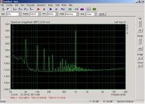
I' ve been using ARTA for speakers measurements and I'm grateful for this tool! Lately, I tried to use it for audio equipment too but I stumbled on a problem that seems to be related to the latest posts. At the pic you can see low frequency peaks that from first sight look like ground loop or psu ripple noise. But it isn't. This "noise" cannot be detected by audacity or my 94db/W/m speakers. It's only there in ARTA. ARTA limp works perfectly.
I use an asus essense stx ii audio card with official asio drivers and windows XP. All windows sounds are dissampled and no windows settings can be done with regard to sound. Only audio device in this computer is asus/asio. Do you think this phenomenon could be happening because of software incompatibility?
Regards
Kostas
Attachments
What measurement is this? Loop from imput to output of soundcard? or Any gear in between?
Considering the low levels involved, if you measured some gear, i would say its psu is really bad...🙄
Considering the low levels involved, if you measured some gear, i would say its psu is really bad...🙄
Hello,
I' ve been using ARTA for speakers measurements and I'm grateful for this tool! Lately, I tried to use it for audio equipment too but I stumbled on a problem that seems to be related to the latest posts. At the pic you can see low frequency peaks that from first sight look like ground loop or psu ripple noise. But it isn't.
Regards
Kostas
Hi,
It is surely a hardware problem (soundcard noise of ground loop induced mains signal). I need more information:
- did you made measurements with loopback connection of soundcard output with soundcard input channel.
- does input is configured as mic. or line input (maybe it is mic input).
Best regards,
Ivo
Thanks for replies!
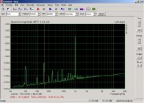
My initial thought was also hardware problem. The sound card has been severely modified. I'm checking on this too and by no means I would like you to put any effort troubleshooting it. The output signal is very low level - 2 ohm I/V resistor directly from PCM 1792 7,8mA pp output. Input is line level. The above pic is with a 6x preamp in the loop. Measurements are not calibrated. Below I attach a DAC out/ line level input loop measurment. Nothing impressive, just DIY fun. But I have a strong feeling that this is not actual noise. If this could reach my speakers it would move the furnitures. And audacity loop recording at idle -no signal- is a DC flat line. Not so with ARTA.
My initial thought was also hardware problem. The sound card has been severely modified. I'm checking on this too and by no means I would like you to put any effort troubleshooting it. The output signal is very low level - 2 ohm I/V resistor directly from PCM 1792 7,8mA pp output. Input is line level. The above pic is with a 6x preamp in the loop. Measurements are not calibrated. Below I attach a DAC out/ line level input loop measurment. Nothing impressive, just DIY fun. But I have a strong feeling that this is not actual noise. If this could reach my speakers it would move the furnitures. And audacity loop recording at idle -no signal- is a DC flat line. Not so with ARTA.
Attachments
Bad hardware hack but nothing to move furnitures nor any thing on earth, just much lowish noise for nothing...
Last edited:
Hi, MagicBus
if you put preamp in loopback, the you have to decouple preamplifier Input / output ground, as I do in ARTA box. Practically, do not connect ground on input channel.
ARTA can't make hum.
Best,
Ivo
if you put preamp in loopback, the you have to decouple preamplifier Input / output ground, as I do in ARTA box. Practically, do not connect ground on input channel.
ARTA can't make hum.
Best,
Ivo
Yes, I've tried this and much more workaround for ground loops. I keep that it can't be software related and from there on I'll fix it. Thank you very much!