How accurate are the online software calculators for figuring out the components for a parallel notch filter? I have found more than a couple on the net. I'll be working on the 2 to 8Khz range.
I'm trying to tone down the highs on my Frugel-horn Fostex Fe108EZ's. I want to attenuate the range from 2Khz to 8Khz at least 3dB. I would need to buy high-quality capacitors, so buying and trying experimentation would get very expensive very fast.
Any advice or pointers would be greatly appreciated. Thanks.
Doug
The calculations are pretty straightforward, so the attenuation you'll get from the filter should be reasonably well represented in the calculator AFAIK. (I'm no expert.)
Here's a calculator you might not have found:
http://lautsprechershop.de/tools/t_ps_schwingkreis_en.htm
Here's a calculator you might not have found:
http://lautsprechershop.de/tools/t_ps_schwingkreis_en.htm
Kristleifur,
Yes, I did miss that one. Thank you. Using this calculator, I think I can shape the filter slope exactly how I want it. Just to be sure I understand this correctly, you use the C and L values to shape the slope and the R value for amount of attenuation? Is this correct, or am I off?
My one question now is how do I figure the amount of attenuation using this calculator? Sorry if this is a dumb question, but I honestly do not know.
Cal,
I'm doing a parallel. According to Fostex's specs on this driver, the impedance slope does not rise at all at higher frequencies. It appears to be 9-10 ohms all the way out. So I don't seem to need to fix that. As I asked above, my one question now is what value of resistance lowers the dB by how much. I read somewhere recently that resistance of 1 ohm reduces efficiency by about 1 dB, but I don't know how accurate that is as this was in relation to a discussion of speaker wires, and we all know how muddy those can get.
Doug
Yes, I did miss that one. Thank you. Using this calculator, I think I can shape the filter slope exactly how I want it. Just to be sure I understand this correctly, you use the C and L values to shape the slope and the R value for amount of attenuation? Is this correct, or am I off?
My one question now is how do I figure the amount of attenuation using this calculator? Sorry if this is a dumb question, but I honestly do not know.
Cal Weldon said:Are you planning a series or parallel notch?
Cal,
I'm doing a parallel. According to Fostex's specs on this driver, the impedance slope does not rise at all at higher frequencies. It appears to be 9-10 ohms all the way out. So I don't seem to need to fix that. As I asked above, my one question now is what value of resistance lowers the dB by how much. I read somewhere recently that resistance of 1 ohm reduces efficiency by about 1 dB, but I don't know how accurate that is as this was in relation to a discussion of speaker wires, and we all know how muddy those can get.
Doug
I think kristleifur got you only part of the way there. The tool you're looking for is a notch filter (the site linked called it a "Frequency Response Leveller") and can be found directly at http://lautsprechershop.de/tools/index_en.htm?/tools/t_ps_schwingkreis_en.htm. I like this calculater a lot becuase it shows the attentuation at various frequencies and let's you check what specific inductor, resistor, and capacitor values will do. It helped demonstrate to me the potential problems of having components (particularly inductors) that are not of relatively close tolerances. For example inductors 10% out of spec will create an audible change over 3 db at and around the target frequencies.
Holdent,
Thank you. I probably would have found this one eventually, as it's on the same site, but thanks for pointing it out. It looks exactly what I need. Also, thank you for the head's up on inductors being so out of spec. I should be able to measure them, and I plan to use pretty high quality resistors and caps, so hopefully it will work out without too much fussing.
Doug
Sounds like the one you are looking fore is "Frequency response leveller" at Strassacker - it shows attenuatin in db
Nice tools, but I also tweak by ear - cap and resistor are easily changed 😀
Nice tools, but I also tweak by ear - cap and resistor are easily changed 😀
Note that you can simulate a notch filter in software before building it, if you've got the attenuation values of the hardware filter.
If you're proficient in Javascript, you can look at the script that runs the filter calculator on lautsprechershop.
Here's an Excel spreadsheet I cooked up from the formula in the Lautsprechershop filter:
http://nemendur.ru.is/kristleifur04/diy/Notch_filter_calc-ROUGH.xls
I don't understand the math anymore 🙂 I don't have time to re-figure it out, but you could be able to make use of it nonetheless. I used this to make a software notch for the Cyburgs Needle, and that sounds fine - the math seemed to work OK 🙂
I started playing around with the calculator on Strassacker tonight. Really neat stuff. It's amazing how you can customize the slope at the lower and upper ends. Luckily, I have pages of readings on these speakers via my trusty SPL meter. I hope to order up a selection of components soon and get to tweaking again. I sure would like to finalize this project though 🙂.
I can't say enough how thankful I am for everyone's help here. Just in the last two weeks, I'm finally feeling that my thinking regarding electricity and sound is starting to gel. It's starting to make sense to me. Not fully yet, but much closer, and since I am so terrible at math I really do need something like the Strassacker calculators for help.
Doug
🙂
So, which is correct?
http://www.carstereo.com/help/Articles.cfm?id=19
or
Parallel Notch Filter Designer / Calculator 😱
And here we may check Impedance:
http://lautsprechershop.de/index_hi...prechershop.de/tools/t_ps_schwingkreis_en.htm
So, which is correct?
http://www.carstereo.com/help/Articles.cfm?id=19
or
Parallel Notch Filter Designer / Calculator 😱
And here we may check Impedance:
http://lautsprechershop.de/index_hi...prechershop.de/tools/t_ps_schwingkreis_en.htm
IME, no. Pretty much as useful as online crossover calculators. They're really only good for a starting guess.
A software crossover simulator will do the trick, but that requires $$ as well as a learning curve, test gear, etc.
A software crossover simulator will do the trick, but that requires $$ as well as a learning curve, test gear, etc.
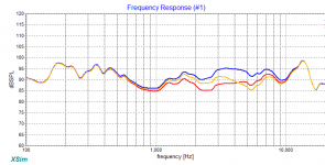
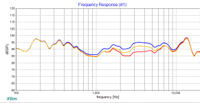
Yes, I know, but this two which I show, make so huge difference, that I'm wondering why...
Next, I simply check with analyzer, and adjust.
Next, I simply check with analyzer, and adjust.
They are wrong or at best misleading. From programmer's perspective, you should not write a software like that.
measure response and adjust accordingly - one leg of an L-pad could be used in some instances to fine tune if R is needed and replace that value with a fixed resistor if things work - some peaks are sharp enough to need no R - I've mainly used "series" filters (confusing as the RLC elements are in parallel with each other)
I've mainly used "series" filters
Me too. Parallel only if utilising available series coil.
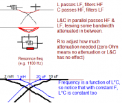
I create notch filters using ears, based on some basic principles, including the resonant frequency formula. In a basic form, I pick any suitable L, and try some C to hit the resonance peak. Then add R to adjust attenuation.
Similar (but different) concept between series and parallel networks.
Attachments
Came on this thread to know how to 'un-tame' my Fostex FE108Sigma horns.
I have the BK108 horn.
Without filter the FE108Sigma/BK108 is a wild thing, too clear (presence effect). [Pass F5 amplifier = low impedance] While with a 300B it does not sound nice at all (uneven, boxy).
The BK108 horn also comes with a filter made by Mundorf. (search for: TESTBERICHT-BK108 Eckhorn.FE108sigma) It consists of
Part 1) of changes:
The calculator gave different values for L and C and R than the stock filter designed by Mr Damde and delivered by Mundorf. The capacitor is higher. And the resistor is very high at 12 ohm, it damps out everything. . . . Damde probably made the filter for an infinity high damping factor amplifier or harsch sounding one - (class-D), but in real life - I have 300B SE triode amplifiers and now solid state triode amplifiers - all with a high output impedance. The 2SK182 is bad bad at about 15 ohms. The 300B ticks at about 3-4 ohms.
So off to change the attenuation.
The calculator gives about the same values as the stock unit for L and C (depending how wide the band is that you want to attenuate, around 2K-5K. The description of the box shows that peak in a graph.
The second part of the BK108 filter is a notch filter, consisting of a 150 uF and a 8,2 ohm resistor, but it is not a notch filter, it is a guillotine. It forces the whole box to a happy 6 ohms impedance. Great for a demo, not in a room.
First of all, I looked at the graphs. And found out that there is a box resonance between 100Hz and 200 Hz (the boxiness maybe). To damp that a notch filter can be used and the notch filter designer says something like 50 uF + 21 mH + 8 ohm : So it looks a bit like I have already on the board.
Altogether, I think I am happy with the changes.
Sound is all over the place now; Well mixed (modern) recordings are great now.
I have the BK108 horn.
Without filter the FE108Sigma/BK108 is a wild thing, too clear (presence effect). [Pass F5 amplifier = low impedance] While with a 300B it does not sound nice at all (uneven, boxy).
The BK108 horn also comes with a filter made by Mundorf. (search for: TESTBERICHT-BK108 Eckhorn.FE108sigma) It consists of
- a parallel filter 0.47 mH//4.7 muF//12 ohm. You read that right . Twelve ohms.
- And there is a notch filter. To give the box a resistive 6 ohms 'look and feel'

Part 1) of changes:
The calculator gave different values for L and C and R than the stock filter designed by Mr Damde and delivered by Mundorf. The capacitor is higher. And the resistor is very high at 12 ohm, it damps out everything. . . . Damde probably made the filter for an infinity high damping factor amplifier or harsch sounding one - (class-D), but in real life - I have 300B SE triode amplifiers and now solid state triode amplifiers - all with a high output impedance. The 2SK182 is bad bad at about 15 ohms. The 300B ticks at about 3-4 ohms.
So off to change the attenuation.
The calculator gives about the same values as the stock unit for L and C (depending how wide the band is that you want to attenuate, around 2K-5K. The description of the box shows that peak in a graph.
- The calculator gives 2,65 ohm for a 6 dB att. So what I did is solder a temporary resistor of 5.1 ohm parallel to the 12 ohm; is 3.6 ohm as a starter. This is great, I will replace it with a single 3.3 ohm I have. Things start to fall into place.
The second part of the BK108 filter is a notch filter, consisting of a 150 uF and a 8,2 ohm resistor, but it is not a notch filter, it is a guillotine. It forces the whole box to a happy 6 ohms impedance. Great for a demo, not in a room.
First of all, I looked at the graphs. And found out that there is a box resonance between 100Hz and 200 Hz (the boxiness maybe). To damp that a notch filter can be used and the notch filter designer says something like 50 uF + 21 mH + 8 ohm : So it looks a bit like I have already on the board.
- I added a 21 mH coil to the Rc to make it a real LCR first of all, for a reduced the effect above 200 Hz;
- I kept the 150mF for now. Now the impedance does not go to the crazy 6 ohms all resistive anymore. I will look in my parts box fto change 150 to 150 muF.
Altogether, I think I am happy with the changes.
Sound is all over the place now; Well mixed (modern) recordings are great now.
Last edited:
Yes Allen. Last night.
The 'hole', suck-out and and lack of presence were gone now.
Longer tests are needed of course. Well known radio and TV sources are great for that. So far so good.
Here is the FE108Sigma/BK108 horn impedance curve.
The BK108 is as far as I understand a standard enclosure designed by Fostex. Interestingly, their own response curve is rather flat.
The 'hole', suck-out and and lack of presence were gone now.
Longer tests are needed of course. Well known radio and TV sources are great for that. So far so good.
Here is the FE108Sigma/BK108 horn impedance curve.
The text says Damde designed the LCR// filter with 0,22mH//12ohm/4.7 uF but what he delivered was 0.47 mH on the board. The text says that is better fit for tube amps like I told him i have. 🙄
The BK108 is as far as I understand a standard enclosure designed by Fostex. Interestingly, their own response curve is rather flat.
Attachments

Last edited:
- Home
- Loudspeakers
- Full Range
- Are notch filter calculators accurate?