Im looking at building this phono stage here and it specifies an oddball capacitor value of 0.0295uf (29500pf)
Ive found a source for a NOS cap but is only rated at 100v/2% and the schematic specifies 400V 1% tolerance, however i did some calculations and the voltage between R5 and R6 is only about 22V, so I should be OK with one rated at only 100V?
Ive found a source for a NOS cap but is only rated at 100v/2% and the schematic specifies 400V 1% tolerance, however i did some calculations and the voltage between R5 and R6 is only about 22V, so I should be OK with one rated at only 100V?
Attachments
Not really because during startup, when the tubes are cold, the cap will see almost full B+ for a few seconds. BTW, did you read note 4? Several combinations are possible to make essentially a .03 ufd....so I should be OK with one rated at only 100V?
EDIT: I don't know you arrived at 22 volts because the resistors that seem like a voltage divider are floating DC wise. So the voltage will be higher.
Last edited:
Read note 4 on your schematic
lol i feel so stupid for not spotting that!
Mind you, its not ideal to parallel a few together and makes wiring a bit less tidy, but I guess this is common when needing to come to a critical value.
Not sure how tolerance would average out, but since its specifying such fine tolerances for the RIAA stage, then you would want it as accurate as possible, 0.03uf -1% gives you 0.0297 and if you had a 0.0295uf cap at +1% you get 0.029795uf at the highest, but there is potential to have something that is up to 0.03.0uf which is even higher again.
Im not sure how critical this is, but you are likely to have a slightly higher value.
Not really because during startup, when the tubes are cold, the cap will see almost full B+ for a few seconds. BTW, did you read note 4? Several combinations are possible to make essentially a .03 ufd.
EDIT: I don't know you arrived at 22 volts because the resistors that seem like a voltage divider are floating DC wise. So the voltage will be higher.
I was treating it like a voltage divider and got around 22v, yes I see note 4.
Now I see the notes say that the tubes run at 100V, so perhaps this is a more closer voltage to expect?
Last edited:
.... I was treating it like a voltage divider and got around 22v....
As was said, at switch-on C1 will come to full 250V before settling to around a hundred volts. The 400V spec is not over-generous.
Is there any calculation to say "0.0295uFd" is the perfect value? If the other cap is 0.01, then 0.03 is not wrong. The 1% difference is a tenth-dB shape EQ error which is mighty small for a tube preamp. (This EQ depends on tube plate resistance, albeit modestly swamped by R5.)
Yeah, ive been reading other threads on the matter and your ears wont even pick anything up under 5% apparently, which is good news since all these polystryene 1% caps that are audiophile grade are selling for ridiculous prices and could cost up to hundreds of dollars for this build depending on the brand and your ears cant even pick up any difference!
Standard capacitance values will not give exactly the desired value in many cases. It is very common to parallel smaller values to end up with the design goal. Nothing bad or wrong with that.
Standard capacitance values will not give exactly the desired value in many cases. It is very common to parallel smaller values to end up with the design goal. Nothing bad or wrong with that.
I thought that the only thing with different values in parallel is their impedance differences in frequency cause it to have poles on the filter. If done right that's good. Although I don't expect ears to be able to hear the difference.
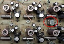
4 x 7500pF 350V SGM-3 Russian silver mica stacked in my preamp
I take its not part of the RIAA stage? I was reading that silver mica are the worst worst to use in an RIAA circuit. Not sure why, but it might be something to do with their ESR?
Not really because during startup, when the tubes are cold, the cap will see almost full B+ for a few seconds.
OP you can get around this by moving C3&R7 before R5, and putting a diode from grid to cathode of V2. Then only C3 needs to be rated for 250V or more, while C1 and C2 can be 100V.
It is more important that the Caps do not differ too much between left and right channel - a+5% cap in one channel and a - 5% cap in the other is not good as this will have an impactYeah, ive been reading other threads on the matter and your ears wont even pick anything up under 5% apparently, which is good news since all these polystryene 1% caps that are audiophile grade are selling for ridiculous prices and could cost up to hundreds of dollars for this build depending on the brand and your ears cant even pick up any difference!
OP can use this: ECW-F4303JLB Panasonic | Mouser Canada
Every cap I've bought in this 5% series tested bang on it rated value. If you're worried, buy 10 and pick the best pair - they aren't expensive.
Every cap I've bought in this 5% series tested bang on it rated value. If you're worried, buy 10 and pick the best pair - they aren't expensive.
Shove a damn 0.033 in there and call it a day.
You won't hear a difference.
Pretty sure I did the exact same thing when I built that. 😀
Yes, matching the channels is more important than having the exact value for the capacitor.
Some silver mica caps aren't very good, some are fine. You have to measure the DA to determine this. Polystyrene caps would be the direction I normally take, but I match them using an HP LCR meter (4263A) and always check the DA.
So, exhale and take a reasonable approach to building your preamp.
-Chris
I used to use PS but I switched to film.
My filter uses 0.1 for one corner, 0.033 || 1000pf in the other corner. I can't tell the difference between mica and film in the 1000pf position. I probably wouldn't notice if the 1000p cap disappeared.
My filter uses 0.1 for one corner, 0.033 || 1000pf in the other corner. I can't tell the difference between mica and film in the 1000pf position. I probably wouldn't notice if the 1000p cap disappeared.
If you can get E24 values, 22 nF in parallel with 7.5 nF will be exact, or otherwise 22 nF in parallel with two 15 nF capacitors in series.
- Home
- Amplifiers
- Tubes / Valves
- Are 0.0295uf capacitors not a thing anymore?