I have searched posts and not found anyone using an Arduino to monitor Bias, HT voltage etc. I would like to check and compare the current thru the four parallel cathode biased valves in my amp and alert me to inconsistencies. Maybe just light up a LED if one is not within the set parameters. Seems simple enough but I havent a clue about the code etc. I would love to know if anyone does!
Hi,
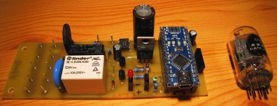
I use an Arduino controller in my GM-70 SE amplifier.
It manages soft start, monitors instant and average cathode current and breaks the HT power transformer primary if it detects any problem.
It also controls LEDs to signal status and power clipping.
This little controller ($10) allows me to use fixed bias without fearing runaway power tubes! 🙂
Attachments
I have searched posts and not found anyone using an Arduino to monitor Bias, HT voltage etc. I would like to check and compare the current thru the four parallel cathode biased valves in my amp and alert me to inconsistencies. Maybe just light up a LED if one is not within the set parameters. Seems simple enough but I havent a clue about the code etc. I would love to know if anyone does!
I use a PIC -- same difference 🙂
I use a PIC -- same difference 🙂
Not quite. With an arduino, you've got the admiration of the duct-tape wielding, POV loving, Maker hipsters. With a PIC you are just solving your problem without needing skinny jeans, fixie bicycles, ironic t-shirts, or pabst Blue Ribbon beer...
Sheldon
😀Not quite. With an arduino, you've got the admiration of the duct-tape wielding, POV loving, Maker hipsters. With a PIC you are just solving your problem without needing skinny jeans, fixie bicycles, ironic t-shirts, or pabst Blue Ribbon beer...
Sheldon
I just googled fixie bicycles, if my daughter sees that I'm finished....
🙂
http://3.bp.blogspot.com/-3teRT90Ptz0/TmD7L6YHSNI/AAAAAAAAAIs/aIyUa_hsCAA/s1600/fixie-bike.jpg
I am not the right shape for skinny jeans and my bike is electric
Please can you at least give me some clues as how to go about this. Hall effect sensor or just measure the voltage drop across a resisitor? Will the Arduino be accurate enough alone or do i need an amplifier between? How am I going to figure out the code?
I am happy to DIY but need a clue before wadeing thru the many POV tutorials.
Much rather read something...
The Arduino can directly measure a voltage between 0 and +5V, with a 10-bit precision (4.9mV resolution). That is a pretty good performance.
To measure higher voltage, you simply use a voltage divider with 1% resistors, and translate it in the code.
To measure a current, you measure the voltage drop across a small value resistor (10 ohm for example).
I will send you my code, I think it would help.
To measure higher voltage, you simply use a voltage divider with 1% resistors, and translate it in the code.
To measure a current, you measure the voltage drop across a small value resistor (10 ohm for example).
I will send you my code, I think it would help.
This all looks like gibberish but it is a starting point.
OMG... and I thought my code was readable...
 😀
😀You have the Arduino reference online, it will help you understand.
I suspect he was not dissing your coding ability, but rather that all code looks like gibberish if you don't understand code.
I suspect he was not dissing your coding ability, but rather that all code looks like gibberish if you don't understand code.
Hence the name 'code' 😀
I suspect he was not dissing your coding ability, but rather that all code looks like gibberish if you don't understand code.
Yeah, I got that, I was joking! 😉
PBR was the drink of the masses in the 1960's -- how it became a yupster beer i'll never know. Maybe they'll bring back Schaefer, Rheingold and Schlitz.pabst Blue Ribbon beer...
"Schaefer, Rheingold and Schlitz. " ... strange, all three are available locally.
Writing code that works is one thing. Writing code that is concise, readable and well documented is another. Regrettably, as I do little programming, I fall into the former category.
PBR is an interesting brewery in that they once owned the market in the USA. During the 60s with TV mass marketing they began changing their recipe and process. Reduced hop rate to reduce bitterness and produce a sweeter more balanced beer was the trend among most brewers at that time. In the 70s PBR tried some new processes to reduce brewing and lagering times. Unfortunately what worked in the pilot runs did not translate to mass brewing and there was a marked change in the flavor of the beer that was not acceptable to the masses. It took 30 years for Pabst to recover from those mistakes.
Last edited:
I use a PIC -- same difference.....Not quite. With an arduino, you've got the admiration of the duct-tape wielding, POV loving, Maker hipsters.
If you're geek enough you can do both. Arduino software and hardware compatible with a 32 bit 80 MHz PIC chip:
Digilent Inc. - Digital Design Engineer's Source
Maybe they'll bring back Schaefer, Rheingold and Schlitz.
When we see the return of Red White and Blue or Falstaff then we know the end is near. We had the untimate in stink beer, Regal, brewed in downtown Miami, but I'm not sure it ever got distributed outside of south Florida. Disgusting stuff.
I did a project for a Microchip / Circuit Cellar magazine contest back in 2007 that used a dsPIC chip to measure and control the bias, allow several choices of operating points, modulate the B+ on the output tubes in real time to improve efficiency (Class H operation) and even test the tubes. The project won a prize, and was published in the magazine. Sadly, I never took the project much further than the basic functionallity needed for the contest, and it has since been robbed for parts. The publication is no longer on CC's web site, so I will eventually put it on my own site.
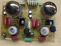
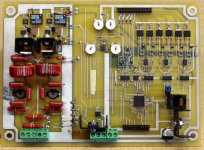
Schematics of the controller and amp are attached. Feel free to copy whatever you can use. My code sucks too bad to publish. Real programmers...even Arduino hackers laugh at me.....and I have a degree in computer engineering!
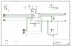
Page 1 is the dsPIC chip and EEPROM for saving settings.
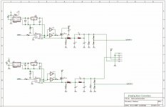
Page 2 is bias controller. SPI commands are sent to the dual DACs which create a voltage from 0 to +5V. The opamps scale that into a 0 to -150 volt bias. There are 6 duplicate circuits. There were 4 output tubes and two drivers under PIC control.
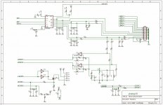
Page 3 is the modulated power supply. The dsPIC samples the two audio inputs and generates a PWM pulse train with a duty cycle equal to the instantaneous audio amp. This circuit uses those pulse trains to control two buck converters that step down the +450 volt supply to the range of +150 to +420 volts in step with the audio. Think of it as a mega SE class D amp. This voltage is the B+ for the aUdio output tubes. The output tubes get only enough B+ to keep from saturating at any given moment. This whole system operates at a 500KHz to 1 MHz rate.
Page 4 is the sensing circuitry. I used an external ADC for monitoring the output tube current, B+ voltage, B+ current, and driver tube plate voltage. I needed the internal dsPIC converters full attention to digitizing the audio stream for the PWM generators. The fet in the lower left is for soft start or B+ shut down if things go wrong. It is tied to the CT on the power transformers HV winding.
The schematic for the tube amp being controlled is shown. There are two conventional stages, abd a cathode follower output stage. A CF output stage was used since it has a very high PSRR. The ability to reject power supply ripple is needed to remove any DSP artifacts that remained on the modulated power supply.
The amp and controller PCB pictures are included.
A few years after publication I received correspondence from the owner of a major tube amp manufacturer regarding an European patent application for a tube amp operated by a microcontroller. Several key claims were taken directly from my original contest submission (including the wording), which had been posted on the internet by CC. I discussed this with the owner, but could not get involved due to the employment contract with my current employer. I don't know the final outcome, but I don't see how those claims could stand.
I have started down the road to building a new design that will be completely controlled by the large ChipKit board mentioned above. I have been using these boards at work for automated IC testing, so it makes sense to use one here. This project will be done in small steps. The first step is bias monitoring and control, and a few of the features that I never got competely ironed out in the 2007 project. Ultimately I plan for a tube stereo power amp of 100+ WPC, a phono preamp (probably a chip) and a tube guitar preamp all controlled by the ChipKit. I will be starting a thread about it as it progresses, but things will be slow for now, and the controller won't be started until the amp is built.
Will the Arduino be accurate enough alone or do i need an amplifier between?
The Arduino can directly measure the drop across a small resistor in the output tube's cathode. I used 10 ohm. You need a RC low pass filter to remove the audio, and a 5.1 volt zener diode clamp to protect the microcontroller from a tube short.
Providing for Arduino based bias control is a bit harder. Some Arduino's provide a PWM based output that could be used to generate a variable voltage, but you would need to keep the 3.3 volt square waves out of the audio. I choose to use SPI to communicate with a multi channel DAC chip. The contest required the use of a Microchip DAC, but I choose TI today. Don't have the part number handy....I am at work.
You still need an opamp circuit to use the variable positive voltage from the PWM or DAC to control a negative voltage for the output tubes grid. Other functions can be controlled with relays or opto-isolators. I use LDR's for controlling the functions in the guitar preamp. Most are specced to 60 or 100 volts, but I have used them in 300 volt circuits without issue at low currents. Soft Pots can be used for low level controls but most are limited to 5 volts or less.
Attachments

Perhaps gibberish was poorly chosen
Thanks for all that, I will see what I can make of it. I really only want to compare four cathodes and tell me if the values are to far apart. More for fun than anything
Thank
Thanks for all that, I will see what I can make of it. I really only want to compare four cathodes and tell me if the values are to far apart. More for fun than anything
Thank
The Arduino can directly measure the drop across a small resistor in the output tube's cathode. I used 10 ohm. You need a RC low pass filter to remove the audio, and a 5.1 volt zener diode clamp to protect the microcontroller from a tube short.
Providing for Arduino based bias control is a bit harder. Some Arduino's provide a PWM based output that could be used to generate a variable voltage, but you would need to keep the 3.3 volt square waves out of the audio. I choose to use SPI to communicate with a multi channel DAC chip. The contest required the use of a Microchip DAC, but I choose TI today. Don't have the part number handy....I am at work.
You still need an opamp circuit to use the variable positive voltage from the PWM or DAC to control a negative voltage for the output tubes grid. Other functions can be controlled with relays or opto-isolators. I use LDR's for controlling the functions in the guitar preamp. Most are specced to 60 or 100 volts, but I have used them in 300 volt circuits without issue at low currents. Soft Pots can be used for low level controls but most are limited to 5 volts or less.
I've been working on something similar using the ARM mBed, it contains these features and more - analogue and digital I/O, PWM, SPI, I2C...
Working on a bluetooth controlled compressor, using the mBed and relay attenuators. The coding software is really straightforward, especially for someone that is coding illiterate like myself.
I highly recommend giving it a go, it is only about £40 and incredibly powerful.
Rapid Prototyping for Microcontrollers | mbed
Congratulations on such a brilliant project George, I hope mine comes out looking a fraction as good as yours!
Cheers
Charlie
- Status
- Not open for further replies.
- Home
- Amplifiers
- Tubes / Valves
- Arduino cathode current HT etc