I've had a couple of people ask for my code, especially the stuff relating to the PT2314.
So in the interest of open source, here we go 🙂
The file: ElectronicTuner.zip is my Arduino project.
- http://www.retrojdm.com/Files/ElectronicTuner.zip
- http://www.retrojdm.com/Files/PT2314_(15_pages).pdf
- http://www.retrojdm.com/Files/Si4703_Breakout.zip
Feel free to do whatever you like with this code, just give me credit in the comments if you use a big chunk of it. If you do anything cool, let me know!
Andrew
IVe signed up specifically to thank you for uploading this. Im planning almost the exact same thing 🙂 Whilst i have no experience with Arduino boards ive done a fair bit of DSP on my uni course, created an automatic feedback suppressor for my final year project. So shouldn't be too hard to pick up 🙂
I'd be inclined to use something more powerful than an Arduino, something that could play FLAC music from a USB hub stuffed full of thumbdrives, or perhaps a 2.5" drive hidden inside an 8-track tape shell.
IIRC there was a thread at MP3car.com on controlling radio modules...
Mp3car.com: Providing the latest news on in-car entertainment, and a community to connect people.
IIRC there was a thread at MP3car.com on controlling radio modules...
Mp3car.com: Providing the latest news on in-car entertainment, and a community to connect people.
You could still use the arduino as the central system control MCU, in fact most headunits still do. even the more poweful ones that have all the bells and whistles still use 8-bit, and some 16-bit CPUs as thier central controller.
But they use DSPs for all the audio/video processing. Same difference if you use an STA016/VS1053, or some of that for MP3 decoding as its a DSP handled specifically for the task.
Just use a DSP to control the audio system/USB and decoding, and use the arduino for the main system control.
But they use DSPs for all the audio/video processing. Same difference if you use an STA016/VS1053, or some of that for MP3 decoding as its a DSP handled specifically for the task.
Just use a DSP to control the audio system/USB and decoding, and use the arduino for the main system control.
It's been quite a while since I've done anything on this, but I've finally had some free time and money to spend on it.
I've changed to the Avago HCMS-29xx alphanumeric displays like in my photoshop mockup.
I'm working on an Arduino library for the VMusic3 that I'll upload later, but for now here's a photo of where I'm at...

And a revised version of my face design...

I've changed to the Avago HCMS-29xx alphanumeric displays like in my photoshop mockup.
I'm working on an Arduino library for the VMusic3 that I'll upload later, but for now here's a photo of where I'm at...
And a revised version of my face design...
Oh, and to answer Extreem's question about the rotary encoders and knobs...
Rotary encoders
From sparkfun.com
https://www.sparkfun.com/products/9117
Knobs
They're from a Kenwood M-616DV micro hifi.
The knob's part number is K29-8822-08
I have an M-616DV, but you could also look at the stereos in your local shop until you find knobs you like, and remember the model number for that stereo.
I phoned up Kenwood's service department and ordered 10 of them. I was emailed an order form to fill out. They worked out at around $2.50 each (I can't remember exactly).
I've finally finished my VMusic3 library 🙂
Oh, and I've organised the PT2314 stuff into a library too.
All the files can now be found on this page:
Arduino Car Stereo - Retro JDM
Oh, and I've organised the PT2314 stuff into a library too.
All the files can now be found on this page:
Arduino Car Stereo - Retro JDM
The one thing your missing is some USB/SD MP3 playback. VS1053 is good for this. Also, maybe an AUX jack hooked to one of the sources, so you can tie your phone into it. Another thing is getting a bluegiga A2DP module instead of the Aux jack and tie that into one of the sources.
You can then code some library to control the bluegiga to set it up for handsfree, or just simple audio streaming 🙂
You can then code some library to control the bluegiga to set it up for handsfree, or just simple audio streaming 🙂
Whoops, I was so excited to finish my VMusic3 Arduino library, that I forgot to mention it IS a USB / MP3 / WMA module 🙂
The VMusic3 uses a Vinculum-II (VNC2) USB host, and a VS1003 MP3/WMA audio codec.
I'd thought of adding bluetooth in the future using a Roving Networks RN-52, and maybe even a graphic EQ using a MSGEQ7, but for now I'm trying to avoid "Feature Creep" before the project is finished.
The VMusic3 uses a Vinculum-II (VNC2) USB host, and a VS1003 MP3/WMA audio codec.
I'd thought of adding bluetooth in the future using a Roving Networks RN-52, and maybe even a graphic EQ using a MSGEQ7, but for now I'm trying to avoid "Feature Creep" before the project is finished.
Hello again!
It's very nice of you to create libraries and such for these kind of things, really appreciate it! 🙂
I'm still struggling with the PT2314, I can't seem to get it to work, there's simply no audio output from it however I try! I've connected it according to the datasheet you've linked in and tried every possible setting using your code for it, but it's still a no go.
Do you have a schematic of how you've wired it all up (in particular the PT2314-Arduino bit)? What type of capacitors are you using etc.? Is there a way of ensure/verify the settings that are active in the PT2314?
I'm sorry for all the questions, but I just want this to work! (I'm starting to suspect that maybe my IC's are all bad)
Thanks again for sharing all your work and hope you find the time to finish it all up soon!
Hey Extreeem,
I didn't realise you'd replied, otherwise I would have got back to you sooner.
Here's a photo of the capacitors I've used:

I don't think that photo will be much help with wiring though. My breadboard is a bit of a mess.
Where the datasheet talks about mylar capacitors, I've used those green ones that look like candy.
The only things I can suggest are:
1. All the GND symbols on the datasheet's Application Circuit are AGND (PT2314 pin 2).
2. DGND on the PT2314 (pin 25) should ONLY be connected to the Arduino's GND.
3. Check, and double check each pin on the PT2314 against the diagram in the PDF
4. Make sure the polarised capacitors are the right way around
5. Make sure you set the volume in the code somewhere
6. If you're setting balance anywhere in your code, do it after selecting a source. Each source has it's own balance settings.
7. Make sure the SDA and SCL pins are wired correctly.
Uno: A4 (SDA), A5 (SCL).
Mega2560: 20 (SDA), 21 (SCL).
8. If you've soldered the IC to an adapter like I have to use it on a bread-board, double check each pin's continuity with a mulitmeter.
9. If you've got any pins etc close to eachother, make sure they're not touching.
[EDIT]
Here's a first (untested) attempt at a breakout board in Eagle:
http://www.retrojdm.com/Files/PT2314_BOB.zip
You may be able to follow that schematic or board layout easier than the datasheet.
[/EDIT]
Andrew
I didn't realise you'd replied, otherwise I would have got back to you sooner.
Here's a photo of the capacitors I've used:
I don't think that photo will be much help with wiring though. My breadboard is a bit of a mess.
Where the datasheet talks about mylar capacitors, I've used those green ones that look like candy.
The only things I can suggest are:
1. All the GND symbols on the datasheet's Application Circuit are AGND (PT2314 pin 2).
2. DGND on the PT2314 (pin 25) should ONLY be connected to the Arduino's GND.
3. Check, and double check each pin on the PT2314 against the diagram in the PDF
4. Make sure the polarised capacitors are the right way around
5. Make sure you set the volume in the code somewhere
6. If you're setting balance anywhere in your code, do it after selecting a source. Each source has it's own balance settings.
7. Make sure the SDA and SCL pins are wired correctly.
Uno: A4 (SDA), A5 (SCL).
Mega2560: 20 (SDA), 21 (SCL).
8. If you've soldered the IC to an adapter like I have to use it on a bread-board, double check each pin's continuity with a mulitmeter.
9. If you've got any pins etc close to eachother, make sure they're not touching.
[EDIT]
Here's a first (untested) attempt at a breakout board in Eagle:
http://www.retrojdm.com/Files/PT2314_BOB.zip
You may be able to follow that schematic or board layout easier than the datasheet.
[/EDIT]
Andrew
Last edited:
Check out page 16 of the Mosa MS6714 Datasheet...
http://www.mosanalog.com/spec/MS6714.pdf
There's a demo board that you can see the traces clearly on.
I actually emailed sales@mosanalog.com a while ago and asked what a demo board would cost.
The reply was "It will cost you USD$90.00".
http://www.mosanalog.com/spec/MS6714.pdf
There's a demo board that you can see the traces clearly on.
I actually emailed sales@mosanalog.com a while ago and asked what a demo board would cost.
The reply was "It will cost you USD$90.00".
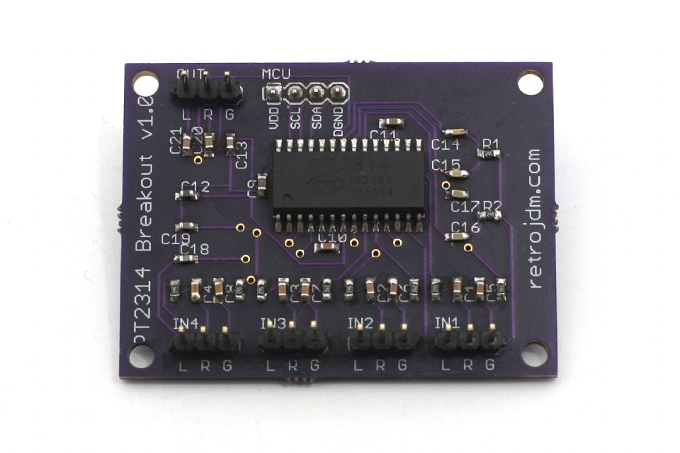
Ok, so I've finally made some progress!
I had my PT2314 Breakout Board printed via oshpark.com and I soldered a bunch of teeny-tiny SMD resistors and capacitors from mouser.com
I can't recommend OSH Park highly enough! Fast, High quailty, AND cheap! (who says you can only have two of those things, eh?)
This was a great test run before I design and print the MEGA shield and face PCBs. You can probably tell from my soldering that this is my first ever PCB 😉
Also, I made a mistake on the silkscreen. The pinouts for IN1~IN4 should read GLR, not LRG.


Here's some downloads in the spirit of open source:
I had my PT2314 Breakout Board printed via oshpark.com and I soldered a bunch of teeny-tiny SMD resistors and capacitors from mouser.com
I can't recommend OSH Park highly enough! Fast, High quailty, AND cheap! (who says you can only have two of those things, eh?)
This was a great test run before I design and print the MEGA shield and face PCBs. You can probably tell from my soldering that this is my first ever PCB 😉
Also, I made a mistake on the silkscreen. The pinouts for IN1~IN4 should read GLR, not LRG.
Here's some downloads in the spirit of open source:
- PT2314.zip - PT2314.zip Arduino Library
- PT2314_Eagle.zip - Eagle files for the PCB
Last edited:
Solder paste and a toaster oven make SMD assembly simple. When the paste activates virtually all small parts pull into perfect alignment with the pads. Sometimes they'll stand up on one pad but that's relatively rare.
I received my Shield and Face PCBs from OSH Park. I've soldered all the components and connectors, and connected everything.
I also just learned the hard way how important "pin 1" labels are on connectors. I'll update my Eagle files and upload them soon.
I had a small error on the Shield PCB where a trace I thought was connected, actually wasn't. You may notice a short green wire as a fix/hack in the photos 🙂
I decided to split the face PCB into two, spacing the display further back to allow for IC sockets, instead of directly soldering those damn expensive Avago HCMS-290x displays.

There's lots more photos here
I still need to:
I also just learned the hard way how important "pin 1" labels are on connectors. I'll update my Eagle files and upload them soon.
I had a small error on the Shield PCB where a trace I thought was connected, actually wasn't. You may notice a short green wire as a fix/hack in the photos 🙂
I decided to split the face PCB into two, spacing the display further back to allow for IC sockets, instead of directly soldering those damn expensive Avago HCMS-290x displays.
There's lots more photos here
I still need to:
- modify the top 4 buttons and glue iPhone 4 power buttons to them
- Get a bigger radio case and mount everything
- Get the faceplate made (probably through frontpanelexpress.com)
Last edited:

For anyone interested, here's the Eagle files for the boards:
http://www.retrojdm.com/Files/ElectronicTunerEagleFiles.zip
These are v1.1 - modified slightly from the photos in my build page:
- Put a little "1" next to the GND pin for the cables between boards
- Changed the audio pin-outs on the PT2314 BOB to "LGR"
- Fixed an error on the Shield where a trace was missing
TDA7419 Board and example code
Hi, I just built a preamplifier for my car with a TDA7419. I wanted the project to be very reliable so I created a custom PCB.
The board has a voltage regulator to take the car 12V down to the 9V that the TDA7419 needs, it routes all of the pins out to headers.
I have example code demonstrating volume, input control, speaker volume control and mix control (to mix in GPS audio).
It worked much better than I expected (great sound quality). I am now working on putting this into my Honda Pilot (real work and life generally getting in the way).
I also had a few more boards built if anyone is interested in one?
See this page for pictures and more details as the project comes together:
https://www.facebook.com/ArduinoAudio?focus_composer=true&ref_type=bookmark
Dan
- Status
- Not open for further replies.
- Home
- General Interest
- Car Audio
- Arduino Car Stereo