I'm confused -- are there 2 separate LF411's, one for each channel? Or is the integrator for the other channel pins 1, 2, and 3 of the LF411 shown?
When you tried the 50V10uF was it in place of C10, or subbed in parallel with it?
My mention of an additional capacitor was as output coupling -- for a test where you allow the other side of the LF411 to set bias -- it won't correct it to zero, is why you need the coupling capacitor.
When you tried the 50V10uF was it in place of C10, or subbed in parallel with it?
My mention of an additional capacitor was as output coupling -- for a test where you allow the other side of the LF411 to set bias -- it won't correct it to zero, is why you need the coupling capacitor.
are there 2 separate LF411's, one for each channel?
Yes, there is one LF411 in each channel (see my picture here).
I wonder if it was better to skip the whole servo circuit and just use a good output cap: but I am not sure what exactly to remove and where to bridge. If you think it would improve the sound quality, please let us know how to do that!
Maybe this could even solve dj_holmes buzzing problem...?
Last edited:
I left everything as is and just tried the 10uf across the final output and ground.
I can confirm that the LF411 is separate from each other. Some of the pins are not used.
The finger fix seems to work better before the opamp rather than after.
I could try and un-solder the opamp? But something tells me its not the issue!
I can confirm that the LF411 is separate from each other. Some of the pins are not used.
The finger fix seems to work better before the opamp rather than after.
I could try and un-solder the opamp? But something tells me its not the issue!
I left everything as is and just tried the 10uf across the final output and ground.
As far as I understood the cap goes not across out and ground but in series with the output...
O.K., I didn't explain very well. The job of the output coupling cap (temporary) would be to remedy the output offset that will occur without the integrator servo. It would also occur if we borrowed the other channel's integrator's output voltage, about 6½ volts, which is what I failed to adequately describe earlier.
Also, either it was too late in the day, or I had too much wine -- didn't notice the pinout of the LF411. Glad you got me to look it up -- it's old enough that it's only available as a single! (Oops 😱)
Have you tried lifting a leg of C2? It's the filter for the 1st stage bias.
If this still isn't giving joy, maybe it would be a good time to post a sample.
Cheers
PS -- sorry I didn't get you this sooner -- a minor cockpit error blew my Chrome instance and it took me a while to re-find your schematic!
LOL! OK I will try lifting C2 but I just discovered something! If I fit the main board back into the chassis the noise is gone! But if I lift it from the chassis even slightly there is massive buzz on left channel.
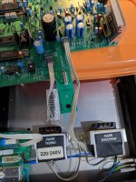
See picture. That's how I'm doing my test.
The lifting doesn't affect the right side only left. Is this some grounding issue?
See picture. That's how I'm doing my test.
The lifting doesn't affect the right side only left. Is this some grounding issue?
Attachments
Do you mean lifting or bending or touching the board when it's in the chassis...?
Do you still have the original caps in there...? I would recommend to replace all lytics and tants (but not with low ESR ones).
The chassis connects to the heat sink of the regulators at the back, but I don't know if that can cause trouble...
Also you don't have the input board connected...?
Do you still have the original caps in there...? I would recommend to replace all lytics and tants (but not with low ESR ones).
The chassis connects to the heat sink of the regulators at the back, but I don't know if that can cause trouble...
Also you don't have the input board connected...?
Last edited:
When the board is inside the chassis its completely noiseless, when I lift it higher and higher it picks up some sort of humming interference! As soon as its lowered right down to where it should fit inside the noise stops.
I know what your thinking but it never did that before. So there is still a fault but disappears when lowered into the chassis and its only left side thats the problem.
I already swapped all caps from left to right.. But if I'm on the right track then I might try this again if you think its the potential problem?
I tried connecting the large heat sink at back to ground when lifted but that did not fix it.
I just removed the input board but its fitted when I was testing..
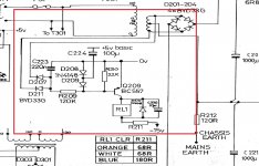
Still haven't fixed this problem. Just a question about this relay circuit. It looks so complicated. Anyone got an idea whats going on?
See here!
You can lift the BJT and switch the relay as shown in my link...
Hi, what benefit is that? Looks even more complicated! Can you explain what you have done please?
In regards to original, Is that whole thing a relay circuit? If so why does it have so many diodes and seems like 3 different power sources?
In regards to original, Is that whole thing a relay circuit? If so why does it have so many diodes and seems like 3 different power sources?
The relay is powered from the -15V rail. If you take out the transistor you can force the relay to open or close by hand. But that's probably not necessary: you can verify with multimeter if it works correctly: it should mute the output for the first couple of seconds after power on...
It looks quite straightforward. D207, D211, and C223 make a full-wave rectifier that produces a negative voltage to drive the base of the Q209 through R209. Tied to +5V rail, C224 enforces a reverse biase voltage at Q209 base at the moment of power-up. C224 gets gradually charged up by R209 and R210 through D209 until the base junction of Q209 becomes forward biased and clamps the voltage at the base to -0.7V, producing a delayed pull-in at the relay. D209 ensures C224 stays out of circuit thereafter, so that when mains supply is out or turned off, Q209 would cut off quickly (note the small value of C223). D208 discharges C224 quickly when +5V collapses, readying it for the next power-up event.Still haven't fixed this problem. Just a question about this relay circuit. It looks so complicated. Anyone got an idea whats going on?
Why change it, is it related to your problem...?That's so over engineered! Anyway to simplify it? And thanks for the detailed explanation!
Its using 5v+ from digital PSU, -15v from analogue PSU and some more power from the 2 diodes from analogue PSU. Thats 3 different rails just for a relay!?
I'm not 100% certain if it is related to my problem but it seems its a problem by itself LOL.
I'm not 100% certain if it is related to my problem but it seems its a problem by itself LOL.
That's so over engineered! Anyway to simplify it? And thanks for the detailed explanation!
For the purposes being served without having to involve a MCU, the circuit is quite efficient and highly reliable. As far as the power rails involved go, only the -15V is really "used". The +5V rail for the digital circuit is in circuit for only a brief moment at power-on, it is then out of circuit the rest of the time. The other "rail" made with the two separate diodes tapping onto the analog psu is rather a sensing circuit for power interruption, than a power rail, with the load current in the micro amp range. I don't see how you can simplify it without compromising the nice and secure muting relay behavior during power cycling and risking loud pop noise in the speakers.
Thanks for the explanation. But that -15v is being shared by the DAC chip, which is just silly as many use separate supplies for the chip itself. Say I was to use a separate 5+ supply and power a 5v relay and remove it from -15v power, will that work? I'm still tackling this nosise in left channel issue but I'm discovering a lot about this DAC!
Make your separate supply a negative one and it will work. Make it -15V and you can keep the factory relay.Thanks for the explanation. But that -15v is being shared by the DAC chip, which is just silly as many use separate supplies for the chip itself. Say I was to use a separate 5+ supply and power a 5v relay and remove it from -15v power, will that work? I'm still tackling this nosise in left channel issue but I'm discovering a lot about this DAC!
- Home
- Source & Line
- Digital Line Level
- Arcam Delta DAC buzzing on left channel