"looks like Cal hooks on the '1054s lower right corner."
I have no idea what that means! I think I already did the screw driver thing. I watched a youtube video!
I have no idea what that means! I think I already did the screw driver thing. I watched a youtube video!

Confirm that R5 and R8 are not stretched. When the -11V was down those transistors might have suffered a hFE loss due to the reverse bias. Their gain would increase with temperature.
Q3,4 and Q6,7 may need to be replaced.
Q3,4 and Q6,7 may need to be replaced.
I checked the resistor in circuit and both measured almost exactly like the other channel. I also swapped the transistors (Q3,4,6,7) from working to non working channel and exactly the same issue!
Uu-uu-gh !😱 O.K., then we'll have to sink teeth into this bad boy. I have a dentist thing in about 12 hours, but I'll take a peek here (if I remember) a couple/3 hours before, and start watching closely starting about an hour after that. If I haven't bodged the arithmetic, that oughta be about your 20:00 hours. I'll clear my schedule for that interval, up to about your 23:00 when I'll have to break off to stir up some dinner for my most excellent wife.
Read you then,
Cheers
Read you then,
Cheers
It was, thanks!
I'm gonna need a few hours to catch back up to where we left off. Will try to complete that tonight so we can get after it tomorrow.
I'm gonna need a few hours to catch back up to where we left off. Will try to complete that tonight so we can get after it tomorrow.
What DC voltage do you have on pins 1 and 6 of the LF411? -- time to start allowing for the possibility of a Zebra here and there.
Pin 1 is 10.2v on switch on.
Pin 6 starts at 6.6 then climbs slowly to 7.9v then very slowly still rising. i stopped it at 7.944
working channel Pin 1 is same but Pin 6 was at 7.2v when left (faulty channel) was 7.9v
Pin 6 starts at 6.6 then climbs slowly to 7.9v then very slowly still rising. i stopped it at 7.944
working channel Pin 1 is same but Pin 6 was at 7.2v when left (faulty channel) was 7.9v
O.K., likely no joy there. Slowly changing voltages as the silicon warms up are to be expected, especially for any parts within a feedback or servo loop.
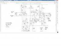
Each of the CCS's with a 22R Emitter resistor (Q6 and Q10) has to dissipate around 310 mW, so will get quite warm, and will need several minutes to reach equilibrium.
Check the DC voltage on C2 -- should be about 7V, Then either unsolder one leg, or hang a probe to your Rigol on it (the node R1 | R32 | C2), set to AC coupling, and see if there is a bit of crackling / popping on it.
The next thing to try removing from effect is the JFET that alters the feedback closure -- it's off the lower edge of the page on the recent PDF. Just unsolder one leg, either Source or Drain. And don't have a speaker connected.
The output stage is a Sziklai pair providing gain of 1,55 (3,8 dBV) to render an Equal-component-value Sallen-Key 12dB/octave LPF. It is outside the primary feedback loop, so any of its components could be the source of the noise. Check C10 by lifting one leg; don't worry that the output offset will wander rapidly -- the LF411's job is to adjust DC bias to zero the output. With ~300 times less capacitance in the integrator it'll surely hop about vigorously.
Past any of those bits, I'd recommend posing a hair dryer on low so that it blankets the suspect area, maintaining it at something like the 'fully warmed-up temperature' so that the symptom subsides. Then judiciously cool one part at a time with freeze mist. Start with the electrolytics, then move on to the CCS transistors that seemed the culprit earlier, then the other transistors. If it's still hiding, start working a small section at a time - 'grid search', until the naughty part can no longer hide and reveals itself.
Cheers
I'm actually very excited by your instructions. I will hopefully get this all done tomorrow and report back. Thanks
I measure C2 it was 6.57v I also checked opposite side it was 6.56v
I could not get any measurements in AC. When I select auto it switches back to DC. When I manually select AC and try and find a signal I get nothing, I have tried tuning dials as much as possible!
I removed the middle pin, source because it was easiest. Made no difference to output noise.
Competently removed C10 and still same noise but a little different.
At this stage Ive already swapped most of the transistors with the other side of the board!
The noise is just unstoppable! Only the power of my finger seems to stop it completely..
Is the other half of the LF411 used in the other channel?
Before trying this, either insert a 10uF non-polar (or a 4,7 or 22 or 47uF if that's handier) at the output -- or confirm that what's plugged in for monitoring has DC isolation:
Try lifting pin 6; then jumper from its pad to pin 1, allowing the other channel to control the offset -- which may be objectionable!
Then carefully compare the volume and timbre of the noise to before.
Cheers
- Home
- Source & Line
- Digital Line Level
- Arcam Delta DAC buzzing on left channel