Hi, my first post here, although I have read many.
I am struggling with a problem with my Arcam power amp so thought I would check out this forum to see if a solution can be found.
I took a risk and bought a faulty power amp on eBay. It was advertised as blowing the main fuse (T1A6) as soon as power connected. And yes it did. I gave it a thorough visual inspection and there appeared to be no visual damage to any components or short circuits. Soldering all looked good.
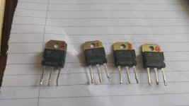
So my plan, having seen a couple of posts about similar issues, was to purchase 4 mosfet transistors, IRFP240's. I got some that were made by Vishay. I removed the four in the amp, which were made by ST (and which showed no sign of damage at all). Same model number. I soldered in the new ones, applied some thermal paste and reapplied the metal clamp. Switched it back on and the fuse went again. Disappointment loomed over.
So I have now gone back to the drawing board and there is one suggestion I saw somewhere that it may be the dual comparator IC (currently a Philips LM393).
Is this likely? Can these be bought of the shelf and fitted straight in? Can the existing one be corrected.
I'd be pleased to have any advise as I do not wish to waste any more money. This should be a fantastic amp.
I already have a 290P and a 290 switched to power amp mode. I wanted to have two 290P's.
Thanks, here's hoping.......
I am struggling with a problem with my Arcam power amp so thought I would check out this forum to see if a solution can be found.
I took a risk and bought a faulty power amp on eBay. It was advertised as blowing the main fuse (T1A6) as soon as power connected. And yes it did. I gave it a thorough visual inspection and there appeared to be no visual damage to any components or short circuits. Soldering all looked good.
So my plan, having seen a couple of posts about similar issues, was to purchase 4 mosfet transistors, IRFP240's. I got some that were made by Vishay. I removed the four in the amp, which were made by ST (and which showed no sign of damage at all). Same model number. I soldered in the new ones, applied some thermal paste and reapplied the metal clamp. Switched it back on and the fuse went again. Disappointment loomed over.
So I have now gone back to the drawing board and there is one suggestion I saw somewhere that it may be the dual comparator IC (currently a Philips LM393).
Is this likely? Can these be bought of the shelf and fitted straight in? Can the existing one be corrected.
I'd be pleased to have any advise as I do not wish to waste any more money. This should be a fantastic amp.
I already have a 290P and a 290 switched to power amp mode. I wanted to have two 290P's.
Thanks, here's hoping.......
Fault finding always begins by gathering evidence and clues.
Did you measure the FET's in circuit before replacing them to see if any had failed short circuit ?
One obvious part to check would be the bridge rectifier/s and see if any of the diodes has failed short circuit.
When testing always use a bulb tester. It will save damaging parts and blowing of fuses.
Where are you looking and finding an LM393 ? There isnt one in the Delta 290. This would lead me to believe the unit has been "repaired" by someone who didnt know what they were doing.
The service manual is available from:
https://www.hifiengine.com/manual_library/arcam/delta-290.shtml
I would wonder if the IRFP240's were fitted in place of the original SM042 devices, and the other modifications werent done.
https://www.hifiengine.com/manual_library/arcam/delta-290.shtml
I would wonder if the IRFP240's were fitted in place of the original SM042 devices, and the other modifications werent done.
Reading the service .pdf, I think I can see a single pair of irfp240 as a quasi complementary output stage.
The last digit (0) is not clear on my screen.
The last digit (0) is not clear on my screen.
Well, there's where to check if the parts in your dead Ebay purchase are the real deal or not.......I already have a 290P and a 290 switched to power amp mode. I wanted to have two 290P's....
Reading the service .pdf, I think I can see a single pair of irfp240 as a quasi complementary output stage.
The last digit (0) is not clear on my screen.
Comparing with other digits, looks like one of those zeros with an oblique line through it, the 8's look different
I am surprised they chose a 5534 as the Dc servo.
Any thoughts on why they selected a BJT input that is fairly fast for this duty?
Any thoughts on why they selected a BJT input that is fairly fast for this duty?
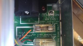
Are you sure you are using a Time Lag fuse? when you say blows when power is connected, I presume you mean at switch on....
Last edited:
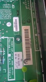
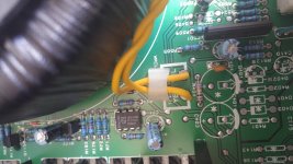
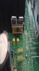
The LM393 sits between the heat sink and toroidal transformer. The 290P may differ from 290?
I can't attach image to reply unfortunately.
I can't attach image to reply unfortunately.
I measured them before removing. Set multimetre ohm check to 2000 and got following readings from each transistor, front to back;
[in this order, 1-2/3-2/1-3 (1 being towards back)]
813/245/569
1320/7k+/570
815/246/569
1323/7k+/570
[in this order, 1-2/3-2/1-3 (1 being towards back)]
813/245/569
1320/7k+/570
815/246/569
1323/7k+/570
Hi Yaycee,
this amp was fitted with IRFP240s to begin with.
I have an old Delta 290 integrated and it has the older style round ones on an aluminium block.
I am trying to work out how to upload photos.
this amp was fitted with IRFP240s to begin with.
I have an old Delta 290 integrated and it has the older style round ones on an aluminium block.
I am trying to work out how to upload photos.
Thanks for the various replies.
Just to confirm a few things;
1. It is a power amp, 290P, number D29P02154; it never had SM042's;
2. I am pretty sure this amp has not been tampered with;
3. There is an LM393 between toroid and heatsink;
4. I am not sure if the transistors were faulty, they just gave dodgy readings when measured in place. They all measure consistently on removal, 701 to 711 between middle and right (no other combinations give readings when they are out of the circuit)
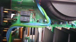
5. The T1A6 fuse is closest to the power input socket on the rear, orange and black wires;
6. I am still trying to find out how to attach an image from my desktop.
Just to confirm a few things;
1. It is a power amp, 290P, number D29P02154; it never had SM042's;
2. I am pretty sure this amp has not been tampered with;
3. There is an LM393 between toroid and heatsink;
4. I am not sure if the transistors were faulty, they just gave dodgy readings when measured in place. They all measure consistently on removal, 701 to 711 between middle and right (no other combinations give readings when they are out of the circuit)
5. The T1A6 fuse is closest to the power input socket on the rear, orange and black wires;
6. I am still trying to find out how to attach an image from my desktop.
I can't attach image to reply unfortunately.
Like this:
To add a photo, files or non standard files.
First click "go advanced" in the box below the "quick reply" message box. Doesn't matter if you decide half way through a message to do that, it carries it forward.
Then click "Manage attachments". Maximise the new Window so that you can see all the text.
Click browse in the first box at the top and find your picture. Repeat for any more pictures.
Click upload... a message appears "uploading"
When complete the files will show as being attached. Now click the small text that says "close this window"
The pictures should now be attached and when you submit your post they will appear.
Make sure your pics aren't too big, a couple of 100k is plenty, and many members object when they are massive and it alters the margins
It tells you in the attachments window what max sizes are allowed.
If you want to attach a file that has a non standard format for example excel, circuit simulation etc then try putting the files in a zipped folder and attaching that.
Photos of components etc
A few helpful photos
A few helpful photos
Attachments
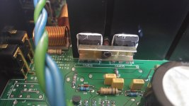
LM 393 probably a modification/addition to the loudspeaker protection circuit. It would be useful to know for sure. Is it in your 290 as well?
Last edited:
Did you check the rectifier for shorts as I mentioned earlier ?
If the LM393 is a known (stock) fault then these cost buttons but its much better to prove by measurement than replace in hope. We would need to see the correct circuit diagram though.
I guess this is where the LM393 mention was:
http://www.diyaudio.com/forums/solid-state/68635-arcam-delta-290-fuse-keeps-blowing.html#post827086
Thanks Mooly, I was looking for it in quick reply and its not possible, had to use post reply at foot of thread. Getting the hang of it, cheers!
Mooly has linked to a 393 controlling the output bias current.
This seems to be an update that is not shown on the .pdf from HiFiengine.
I wonder if it's on an Alpha9 amp .pdf?
This seems to be an update that is not shown on the .pdf from HiFiengine.
I wonder if it's on an Alpha9 amp .pdf?
More images and update
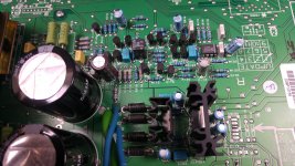
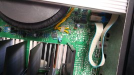
Its a pity that there was no separate service manual for the 290P but it shares the same pcb and layout as the 290 so they didn't bother.
I am very rusty at my circuit diagram reading plus the seven diagrams at the back of the manual are not helping much. I think I need to look at the fourth one, "Power Amp & Amp PSU" 11-May-1993
Here are some images of the board, first being the right channel circuitry.
I only have a M830-B Sinometer multimetre from Maplin, no other measuring/testing device.
Attachments

- Status
- Not open for further replies.
- Home
- Amplifiers
- Solid State
- Arcam Delta 290P keeps blowing fuse