OK think follow, only bit that is a little confusing is due to the service manual suggestion measuring across R1 and setting voltage to 2.3-2.8mV. I will uploaded this image the pot is turned fully anticlockwise. By preset are you suggesting turning up the pot to is reaches 10K?
Just want to be sure at this stage, so don't damage any of the work!
Just want to be sure at this stage, so don't damage any of the work!
Go off what the manual says.
2.3mv is a current of 20 milliamps which is obviously its target value. Theory and practice offer differ in commercial designs due to constraints of heat sinking and ensuring cool running and so on.
To get the preset at the correct end just put your meter on ohms and measure between B and E of Q15. You want the preset turned to the end that gives the highest resistance. Swap the leads around and just check that the result is the same even though the actual readings will differ wildly.

Just for anyone following this thread here is the image of the LH side of the 8P amp, the trim pot is set to minimum.
Will measure as you suggested thanks !
just checked Q15 and circuit tracks, from the picture pov Bottom left leg and middle leg connected and go up B of Q15, bottom right to E of Q15 and did continuity test and verify this.
Service manual states, "From cold and with no load turn both IQ presets (RV1 & RV101) down to minimum (fully anticlockwise) and set voltage drop across R1(R101)....."
Service manual states, "From cold and with no load turn both IQ presets (RV1 & RV101) down to minimum (fully anticlockwise) and set voltage drop across R1(R101)....."
Sounds good to me. Their reference of 'minimum' is referring to minimum current that will flow in the output transistors rather than minimum resistance.
Jut take it slowly, checking and confirming each channel adjusts OK, then repeat the procedure on full mains.
Jut take it slowly, checking and confirming each channel adjusts OK, then repeat the procedure on full mains.
Hi Mooly,
Have completed the work on the Alpha 8P, took it very carefully. Did the bias checks, first setting the resistance across Q15's B & E to an approx 10K having removed the short across it first. Tested and let the Amp settle for 5 mins (no load) at 2.5mV across R1, did the same procedure RH stage and for R101.
Replaced the bulb with a the correct fuse and retested both R1 and R101, everything looked good, left it like that for 5 mins and did final DMM checks. Fitted the case and have tested the Amp at low volume output and all is working as expected. I will be gentle to the Amp for a few more days running it up for couple of hrs at the time.
Many thanks for your great help !!!, can not thank you enough as I was about to give up with this Amp. I feel I have come to know my Alpha 8P a whole lot better !! However I do wonder why the diode failed in the first place?
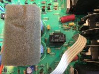
For those interested here is a picture of the Amp with bulb in place and testing R101 with DMM for bias set up of the RH stage before full mains testing.

Have completed the work on the Alpha 8P, took it very carefully. Did the bias checks, first setting the resistance across Q15's B & E to an approx 10K having removed the short across it first. Tested and let the Amp settle for 5 mins (no load) at 2.5mV across R1, did the same procedure RH stage and for R101.
Replaced the bulb with a the correct fuse and retested both R1 and R101, everything looked good, left it like that for 5 mins and did final DMM checks. Fitted the case and have tested the Amp at low volume output and all is working as expected. I will be gentle to the Amp for a few more days running it up for couple of hrs at the time.
Many thanks for your great help
!!!, can not thank you enough as I was about to give up with this Amp. I feel I have come to know my Alpha 8P a whole lot better !! However I do wonder why the diode failed in the first place?For those interested here is a picture of the Amp with bulb in place and testing R101 with DMM for bias set up of the RH stage before full mains testing.
 excellent, well done.
Bridge rectifier failure is quite an old fashioned fault really... it happens though, along with lots of other things as well.
Alpha 7 main amplifier intermittent LH channel
Different problem than 8P I posted about earlier and now fixed. The Alpha 7 is June 1996 model, had from new.
This issue I thought I had solved by renewing some of the old solder joints on the board that looked dry but the problem has returned.
The problem is with the LH Channel which sometime comes up when the Amp is switched on or will work after a little while when warm and will then drop out. I can sometimes “jump” start the channel by unplugging and re-plugging the audio source by creating “channel buzz” – not sure how to better describe it.
I have had a thorough visual examination of the components and can not see any obvious issues (no caps are bulging, or resistors cracked etc). I have followed the circuit diagram from SW305 (the source selector) to see if there are any other issues, nothing obvious.
Checked the bias voltage on R1 and R101 and they are as expected for an Alpha 7 around 3.5mV. I noticed LK901A is not part of this design though shown on the schematics of the Phono input/output stage of the service manual.
Is this one for Arcam to solve? or could someone make a recommendation?
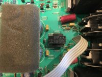
Does the amp use a relay for the speaker feed ?
If so, and if the problem is just audio drop out then its possible the relay contacts are tarnished. That also fits with you 'jump starting' that channel. The extra voltage output created by doing that can punch through the insulating layer on the contacts and it then appears OK until the next time.
If so, and if the problem is just audio drop out then its possible the relay contacts are tarnished. That also fits with you 'jump starting' that channel. The extra voltage output created by doing that can punch through the insulating layer on the contacts and it then appears OK until the next time.
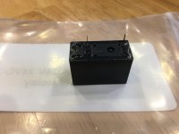
Yes the Amp use this - RELAY G5Z-2A-E 24V. From the service manual.
Think this is a close match for this component.
G5V-2 12DC OMRON ELECTRONIC COMPONENTS, Signal Relay, G5V-2 Series, DPDT, 12 VDC, 2 A, Through Hole, Non Latching | Farnell element14
Think this is a close match for this component.
G5V-2 12DC OMRON ELECTRONIC COMPONENTS, Signal Relay, G5V-2 Series, DPDT, 12 VDC, 2 A, Through Hole, Non Latching | Farnell element14
You need to prove it first, don't just change it on spec.
The one you linked seems to be a 12 volt coil, not 24v.
The one you linked seems to be a 12 volt coil, not 24v.
Some relay deja vu here. Note jaycee's comments on trying to replace it and this applies to all the Alpha One, 7 & 8 series:
http://www.diyaudio.com/forums/solid-state/210428-arcam-alpha-8r-relays.html
http://www.diyaudio.com/forums/solid-state/210428-arcam-alpha-8r-relays.html
Thanks Ian & Mooly,
I spotted this thread while hunting on the web last night for a supplier of the Omron G5Z-2A reply (I could not, looks to be obsolete). The issue mentioned sounded surprisingly similar !
Unfortunately like most forum threads there is great suggestion but not comment from the person with the issue if the fix actually worked!
Looking at the spec of the Finder 40.52 it has a different internal config to the Omron, with pins 12 & 22 not in use so would need to be cut off to fit and the layout of the pins will not be a drop in match.
I have emailed Arcam support to see if they can offer a suggested solution to replace this relay type. If they do I will post their response here and the fix once completed.
Can the relay cover be removed without damage, do you think? The relay seems to be very small for the task and probably under-rated for the duty, so perhaps the cover is not removable, but if it can be popped off by levering the cover sides upwards from the base with a bent piece of steel wire, a long, flathead nail or such, it might save a lot of grief in searching for unobtanium or struggling to adapt something that isn't the same anyway.
A few small card strips wet with Isopropyl alcohol or a quality contact cleaner and pulled several times between the contacts, with a little clenching force, usually works wonders.
A few small card strips wet with Isopropyl alcohol or a quality contact cleaner and pulled several times between the contacts, with a little clenching force, usually works wonders.
Omron G5Z-2A replacement
Hi Ian and Mooly,
It was some while ago I posted on the issue of the LH speaker not coming up when the relay clicked, reason being is the Alpha 7 has been working OK since I posted until 1 wk ago when the issue returned.
I did speak to ARCAM support about sourcing a replacement part as this relay is obsolete but without success as they were unwilling to recommend a replacement part due to Health and Safety of self repair (?!) and insisted I contact one of their recommended repairers (I did not take them up on this offer). But I did research the web at the time to see if this part is still stocked by someone, it was so ordered the part new.
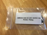
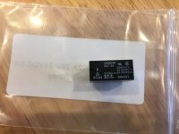
Yesterday evening I replaced the relay and can report that both speakers are working again. Looking at the failed relay it is a sealed unit so no way to remove the cover without breaking the casing. So cleaning the contacts is not a viable option.
I enclose some pictures of the part and the before/after of new relay replacement.
Hope this helps others.
Thanks for your help guys.
Hi Ian and Mooly,
It was some while ago I posted on the issue of the LH speaker not coming up when the relay clicked, reason being is the Alpha 7 has been working OK since I posted until 1 wk ago when the issue returned.
I did speak to ARCAM support about sourcing a replacement part as this relay is obsolete but without success as they were unwilling to recommend a replacement part due to Health and Safety of self repair (?!) and insisted I contact one of their recommended repairers (I did not take them up on this offer). But I did research the web at the time to see if this part is still stocked by someone, it was so ordered the part new.
Yesterday evening I replaced the relay and can report that both speakers are working again. Looking at the failed relay it is a sealed unit so no way to remove the cover without breaking the casing. So cleaning the contacts is not a viable option.
I enclose some pictures of the part and the before/after of new relay replacement.
Hope this helps others.
Thanks for your help guys.
Attachments
 well done.
A zillion posts have come and gone since you were working on this but I do remember the gist of it all.
Good result.
Arcam Alpha 8p
So, I got one of these with simlilar problems, anyone willing to help?
I will upload pictures and a explicit explanation of the problem(s) later on.
Cheers!
Chris
So, I got one of these with simlilar problems, anyone willing to help?
I will upload pictures and a explicit explanation of the problem(s) later on.
Cheers!
Chris
Got this from a dude who after putting in new caps gave up on it.
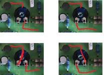
2 big Mundorfs, 6 Tonerex and the Elna Silmic marked with green. Elnas are all 25v 100uf, I can´t confirm if they are all correct. Scematic is listed as 7r and this is a 8p poweramp. There are 3 rubycon 10ufs still sitting, originals I presume.
Started it up, amber light, relay click and no green light. It stayed amber. Procedeed to set bias when the fuse blew, repeated and it blew immediately on startup again.
MOSFETS at Q1,2 measured strange so I removed them and ordered new ones.
LK between Q1 and R1 was burnt black so there´s another clue as what up; marked red in pic 1 and a closer look in pic 2. I cleaned it up though 🙂
Unsure about measuring the transistors, I have new ones around though. Except that 2240 one at Q120
So yeah, maybe you guys have some tips, I am very much a beginner at this.
Cheers!
Chris
- Home
- Amplifiers
- Solid State
- Arcam Alpha 8 DEAD