As that did not work decided to remove Q4/5 again to see if I could isolate which is the problem channel. Amp powered up and lamp went out. So it must be an issue with the left hand stage.
I also removed both IRF540 on the left stage to check to see if there is any issue with them now (even though both are new), both appeared to work OK when doing a diode test on the source and drain then applying the positive to gate switching on the device. By touching the drain and the gate the charge is released and the device is off. Thought this might help.
OK, a couple of possibilities here.
Firstly make certain that the transistors you have replaced are in fact all the correct types and fitted correctly.
You've tried one channel and the bulb lights. Try the other channel in the same way and see if that behaves the same. Its unlikely you would have a genuine fault on both channels.
Its possible there isn't actually a problem at all at this stage and that the current draw of the amp is just tipping the bulb over the point at which it lights. We need to be sure though and that means some real test and measurement.
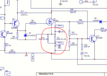
The voltage between TP10 and TP12 (so that's the voltage across R17 at the moment with the transistor shorted) determines how hard the output stage conducts.
I would expect around 1.5 volts between those two points but can you check it.
Also what wattage bulb are you using ?
Lets see what all that throws up.
Firstly make certain that the transistors you have replaced are in fact all the correct types and fitted correctly.
You've tried one channel and the bulb lights. Try the other channel in the same way and see if that behaves the same. Its unlikely you would have a genuine fault on both channels.
Its possible there isn't actually a problem at all at this stage and that the current draw of the amp is just tipping the bulb over the point at which it lights. We need to be sure though and that means some real test and measurement.
The voltage between TP10 and TP12 (so that's the voltage across R17 at the moment with the transistor shorted) determines how hard the output stage conducts.
I would expect around 1.5 volts between those two points but can you check it.
Also what wattage bulb are you using ?
Lets see what all that throws up.
Thanks for the reply, the bulb is the old style 60W homebase one I found in the spare bulb draw 🙂
Just want to make sure I have explained myself well, I rebuild the circuit with all 4 transitors in, on turning the power on the bulb lite and was on, the relay did not do the big click and the led did not change to green. I triple checked the transitor types before soldering them in. I have also tested them on the Hfe on the DMM and they work showing their gain outputs.
By removing the LH transistors for Q4/5 but leaving in the RH stage ones in the Amp powered up as expected. Nice loud click from the relay and the led went green.
This evening I will resold the Power Transistors Q1/2 and Q4/5 then I will remove Q104/105, with the 60W bulb in place power on and see what happens.
Before unsoldering RH transistors would like me to measure across R117 (TP23 and TP24 )? Thank you for your patients on this problem I though it was nailed with the issue on diode D203.
60 watt is a bit on the low side. The bulb allows current to be drawn and up to a certain point stays cool and presents as a low resistance. As the filament heats its resistance increase dramatically thus limiting the current (and lighting the bulb).
I don't know how good your desoldering and soldering skills are but the one thing we need to avoid is damage to the board and print, however... if you are confident in your abilities 'swapping' what are doing between channels is good method.
It sounds like the right channel is basically functional and you could try that one channel with a speaker and music at this point (very low level).
And as I mentioned, its quite possible there isn't a problem now and that its just the bulb tripping things up.
If you have a 100 watt bulb use that, or if you have another 60 watt then tag that in parallel to the 60 you have.
Just got home and tried the Alpha 8P with a feed from the Alpha 7 Amp, Bi-wired to the RH speaker (8P driving Bass and 7 driving tweeters), both Amps on green LEDs and full music heard from RH speaker. Volume on main Amp at 8 o'clock position so is low. So RH stage of 8P is definitely working. I've had a quick look and can't find a 100W bulb (only low energy halogens) or any other spare bulb single holders but I do have an old ceiling light in the loft with three bulb holder, I think this might do?
My soldering is OK but the tracks are looking a little sad as I have removed these transistors quite a few times now. I'm not sure if you want me to de-solder the RH Q104/105 now or not?
My soldering is OK but the tracks are looking a little sad as I have removed these transistors quite a few times now. I'm not sure if you want me to de-solder the RH Q104/105 now or not?
Right hand channel is sounding like a runner then at this point. Lets keep that channel intact.
And just to confirm... you haven't done any work on any of the circuitry to the left of Q4 and Q5 (replacing transistors and so on) apart from us deliberately shorting Q15.
If that's the case then I think we have to try a 100watt bulb if you have one. Its the least invasive first step.
And just to confirm... you haven't done any work on any of the circuitry to the left of Q4 and Q5 (replacing transistors and so on) apart from us deliberately shorting Q15.
If that's the case then I think we have to try a 100watt bulb if you have one. Its the least invasive first step.
At the start of this 8P Amp fix thread I mentioned this :- Along with all 4 IRF540 PBF replaced I also replaced Q(10)3, Q(10)4, Q(10)5 and Q14 & Q114 in all 8 transistors. You pointed out that I should probably have looked for the issue rather than a whole sale change of these components (point taken!).
Currently LH 2x IRF540's are out and so are Q4/5. I tested both Q4/5 with Hfe on the DMM they are good.
Currently LH 2x IRF540's are out and so are Q4/5. I tested both Q4/5 with Hfe on the DMM they are good.
OK. So that all sounds hopeful.
The fact the bulb lights only when Q4/5 were refitted suggests the output stage was behaving correctly. If Q4/5 are good (they are) then that means the only reason the bulb lights is because of the voltage dropped across R17. So at this point its still possible there isn't a problem at all.
If you have a 100 watt bulb then that is the safest option to try first. That's with all parts refitted.
If you haven't then we need to look at temporarily reducing R17 to pull the bias voltage down a little.
What I'm trying to avoid is you powering it up on raw mains and it going pop. We need to be as sure as we can that its all working correctly first.
Refitted Q4/5 and IRF540, have two 60W bulbs in parallel. Turned on the the amp both bulbs glow and do not go out, the relay clicks and led turns green. Voltage across R7 2.07v
That sounds fairly promising.
I know all this testing may seem long winded but its the safest overall approach.
Can you measure and compare the voltage across these two resistors. On my diagram that's between test points 14 and 15. The voltage will be very small, perhaps only 10 millivolts or so.
Both channels should be similar.
Also the voltage across the speaker outputs should be near zero. The relay has to click and engage for that to be measureable.
Attachments
Also checked voltage across R01 and R101, R1 is 0.14v and R101 0v. Also the IRF540's on the LH side are warm and the RH are cool?
The left channel is drawing significant current.
What about the voltage across the speaker outputs. Is that zero for both channels ?
What about the voltage across the speaker outputs. Is that zero for both channels ?
Speaker outputs on LH side 0.0005 and on the RH side 0.0001 but its fluctuating. Heat sink on LH getting very hot now!
Its the voltage across the speaker outputs at the back of the amp that we need to confirm as being zero. That's a good clue as to the overall function of the amplifier.
RV1 should have no volts across it because we have the transistor shorted out. If you are seeing voltage across it (across... that means one meter lead on each end of the preset) then something is amiss with the print in that area.
Make sure you have no open print in that area. The voltage between the two crosses should be similar for both channels.
Make sure that with the transistor shorted that you can measure continuity from the top of R17 to the base of Q4, and from the other end of R17 to the base of Q5.
Keep referring to the diagram and it will make sense.
Going to have to leave it for tonight. Take it slowly and check the print methodically for any breaks etc where you have been working.
Attachments
Speaker outputs on LH side 0.0005 and on the RH side 0.0001 but its fluctuating. Heat sink on LH getting very hot now!
Let it cool off.
Voltage wise that's good, it shows there is no 'hard' DC fault swinging the output to one rail or the other and that the basic function of the amp as whole is basically working.
Thought you would like to know before closing for the night, checked the above suggestions top of R17 to the base of Q4, and from the other end of R17 to the base of Q5, Q4 fine but Q5 not... hmm ... checked circuit and continuity the from B of Q115 (or the short lead) to B Q5 worked OK (a buzz) but from bottom of R17 not, followed circuit tracks from bottom of R17 to C of Q15 no continuity, looking under magnifying glass and could see a poor solder to the short circuit. Resoldered and test from bottom R17 to B of Q5 and get a buzz !!!
Powered on Amp both lamps on then off, Amp comes on as it should. Will check voltages again but expect this was the issue. As you say the Amp is OK just the short across Q15 not working (my fault).
Will try with Alpha 7 and both speaker (volume low)
Powered on Amp both lamps on then off, Amp comes on as it should. Will check voltages again but expect this was the issue. As you say the Amp is OK just the short across Q15 not working (my fault).
Will try with Alpha 7 and both speaker (volume low)
My final post for the night, checked R17 and R117 , they read 4.25v and 4.32v. R1 and R101 are both in the very low mV range. Bulb goes out after initial inrush glow.
Have tried the 8P Amp with the the Alpha 7, both speakers Bi-wired with 8P driving bass speakers. Sound heard on both, volume of driving amp very low not to over do it.
Have tried the 8P Amp with the the Alpha 7, both speakers Bi-wired with 8P driving bass speakers. Sound heard on both, volume of driving amp very low not to over do it.
That's great 
When you are happy with the soldering and that all the joints are sound then we move on to adjusting the bias current. The manual should give a procedure and a value but what it comes down to is adjusting for a given voltage across those low value 0.22 ohm resistors R1 and R1a.
A typical current would be around 100 milliamps and that would mean a voltage of around 10 to 11 millivolts across those resistors.
Here's the method.
1/ Be 100% sure you are happy with all your work so far 🙂
2/ Remove the short from the transistor on just one channel.
3/ Set the preset such that it is at maximum (10k) resistance. You can check that by measuring resistance between the base and emitter of Q15. Because of interaction with other parts you wont see full 10k + the 3k9 of R52, but you will be able to gauge which direction gives the highest resistance. Try it with the meter leads both ways around as well.
4/ Switch on and monitor the voltage across those resistors R1/R1a (meter leads directly across them).
5/ Adjust for around 10mV (0.01V). The bulb may start to glow a little.
6/ If that is OK then turn the preset back down again.
Leaving that channel repeat the procedure for the other channel turning the current back down when you have confirmed its going to be OK.
Now we remove the bulb and run on full mains and set the bias to the required value. Monitor the current as the amp warms. Its normal for the bias to wander a bit.
- Home
- Amplifiers
- Solid State
- Arcam Alpha 8 DEAD