O.K. Q8 posible, try and measure B-E here. Also time to eliminate the FET and servo. Short it out drain to source, in other words a link from R49/50/19 junction to Zero volt line. RV1 for minimum current. The amp wont be perfectly balanced for various reasons, but I would think output should be within a couple of volts of zero.
If you add a couple of wires across the FET you can short it out when the fault appears and see if output changes.
If you add a couple of wires across the FET you can short it out when the fault appears and see if output changes.
I'd be surprised if the servo is the issue.. but to disable it unsolder R49. Similarly with the FET, simplest way is to unsolder it.
I'd check the zener D5 and the capacitor across it.
I'd check the zener D5 and the capacitor across it.
Hello again Jaycee, I sense a result here. Just trying to cover all "bases" so to speak. Only reason I say short it out is in the slight chance IC1 is playing up or losing it's supply. I agree, it's very unlikely but it eliminates it.
Forgot to mention - I did short out the source and drain on the FET while it was in the fault state, but still -36V on the output, so I think that IC1 and that part of the circuit is OK.
Left the amp on with LED's wired up for about three hours last night, but still wouldn't go faulty again (several attempts with the hairdryer didn't help, and neither did wiggling any components make it go faulty, so dry joints don't appear to be the cause). Will be leaving it switched on with the LED and bridge on the output today, checking regularly for the the fault state and checking voltages, etc. as soon as I can.
Left the amp on with LED's wired up for about three hours last night, but still wouldn't go faulty again (several attempts with the hairdryer didn't help, and neither did wiggling any components make it go faulty, so dry joints don't appear to be the cause). Will be leaving it switched on with the LED and bridge on the output today, checking regularly for the the fault state and checking voltages, etc. as soon as I can.
O.K. then, -36 on outputs and -36 on Q7/8 collector points at Q8 and maybe Q7. The reasoning is, if Q8 went O/C then Q7 would be turned on via R24 and pull the outputs hard negative. Similarly if Q7 were becoming very leaky when hot it would also pull the outputs down. The transistors that fail, particularly intermitantly are the ones that run hot 99% of time.
That points at likely Q8, in that case - I'll be checking the voltages, and voltage drops as soon as I can and report back with details. But Q8 and Q108 do run hot when it's running and working as it should (too hot to leave a finger on for a long time). Q7 and Q107, by comparison, are relatively cool.
I remember my old car power amp "circa 1983" had the same sort of intermittent fault, I searched the board for hours for a dry joint, without success, then in the corner of my eye I spotted the problem, one of the output transistors had a fractured pin, fortunately there was about 6mm of pin left on the device enabling me to substitute the rest of it for a short length of hookup wire. I will bet you have an intermittent open circuit condition somewhere in your signal path.
Like you, Mooly, I'd like to get the voltage drops measured to ensure that I really have found the fault before just replacing them. Don't fancy blowing up any more speakers!
As for broken wires on the component legs, Muff, wiggling all the components in the suspect area gave no fault, so I'd be surprised if this were the case. Still a possibility, however.
As for broken wires on the component legs, Muff, wiggling all the components in the suspect area gave no fault, so I'd be surprised if this were the case. Still a possibility, however.
True. You could go grab a non conductive probe, some sort of hard plastic "nylon" have the amp on and connected to a couple of junk speakers, even if you have to go buy a couple of nasty $15.00 drivers, hook everything up and with the amp on and access to the copper side of the board go through it systematically applying pressure to points on the board with the probe, I have had success this way in finding intermittent faults in the signal paths of all sorts of audio stuff, IF the problem is mechanical in nature.
Thanks, Mooly... once I've confirmed the fault, I'll get hold of a couple of those and swap them out. And yes, checking the pinouts is definately a wise thing!
Well, the amp has been on now for six hours and the fault state hasn't returned (or at least, the LED hasn't been on for the numerous occasions I've been checking it).
The LED/bridge *is* wired correctly (checked with a PP3, both ways round) and I've now plugged in my MP3 player to the phono inputs of the amp and left that playing. Turning the volume up to full causes a flickering of the LED, as expected. Also, I've left my multimeter probes in the speaker outputs and switch the meter on every time I check, to confirm that the speaker output isn't at -36V again.
I've just re-adjusted RV1 to set 9mV across R41/42 and let it work like that for a while... at some point, the fault just has to show up again...
Intermittent problems really are a pain to fix, aren't they!!!
They sure are, but we like a challenge 🙂 . While you are waiting for it to go faulty heres a run down of possible scenarios. If it does oblige try not to turn off. Use the LED indicator to show the fault is still there and measure. It sometimes helps to think of what the voltages will be when it's faulty, so we get output -37. Q14 base -37.7 Q12 base -38.4 . Somewhere the feedback loop will be trying to correct this (but with the fault can't) and so Q8 should be turned hard on, any voltdrop across R27 indicating base current following in Q8. It's just another way of looking at it.
Once I catch it, I already have pen, paper and a list of voltages already written down to check. So I can get at much as I can as quickly as I can!
In terms of not switching it off, I'll be avoiding that unless I have enough measurements to make some sense of it... however, last night, when the faulty state happened, it switched back to 'normal' while I was measuring voltages - such is the behaviour (see original e-mail and the 'pop' to hum - which is obviously when it switches to -36V - and the 'pop' back to playing music again).
Hence the list of points to measure as quickly as I can when it hits the fault state!
Thanks for the example... I think I understand that; I'm much better with digital circuits with zeroes and ones (5V/3V) rather than analogue stuff, so I'm having to think a little harder than usual! 😉
Would Q6 and Q7 not be able to cause a low base current to Q12 - if Q7 is on, and Q8 off, then wouldn't that also pull Q12 BASE down to -36V? If Q8 is hard on, then presumably it wouldn't be quite -36V at TP17/19 as it'd be a proportion of the voltage drop across R27, R28 (in parallel with R29/RV1) and R30.
(The 'dots' joining the wires on the circuit schematic aren't 100% clear so I'd need to double-check the PCB to see whether some bits really are joined or not!)
Exactly, you've got it ! You see if Q8 has base current following, and there is a volt drop across R27 and the collector of Q8 is at -37 then it's O/C .
just wanted to say to wprice99 i admire your perseverance and especially your patience on this amp. with me it probably would have been launched across the room at high velocity immediately after it blew up that speaker.
and to Mooly, your posts on this thread are like watching a good doctor guide his intern through a complex operation. i wish i had someone like you around when i was first learning electronics!
idea: wire up a small buzzer or piezo doorbell in place of the LED. That way if it goes -36V when you are out of the room, you'll know.
best of luck!
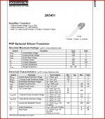
When you take a step back, and look whats going on I am still sure it's Q8, Q7 Q11 or Q12 thats playing up. If Maplin have in stock the 2N5401 and it's complement 2N5551 it's worth getting a couple of each, they will work as the drivers.
- Status
- Not open for further replies.
- Home
- Amplifiers
- Solid State
- Arcam Alpha 3 Left Channel broken...