Too early to celebrate: after a couple of hrs right channel developed bad noise, like crickets chirping ))).
Yep. But it’s not unusual with these “marvels of excellent engineering”, s one ARC fan told me. This was one channel going into oscillation. Perhaps because the gain is so f-n crazy high. My amps were overloaded I think. I can only use up to 3 clicks in this SP-8 volume control. Total BS. The only way to use it is put attenuators on amps input. Which will deteriorate SQ for sure. Yes, you can lower the gain on SP-8 by removing a feedback resistors, but even ARC will tell you this will make preamp unstable. So there’s a little bit of hum on output with this crazy gain. With attenuators there’s none. I think it’s possibly coming from unshielded (!) output wires. Or may be from PSU. Earlier versions had 200uf/450v, this one has only 100uf. I need a break from it…
I think the notes on the schematic say to add an additional 39.2K resistor in parallel to the current feedback resistor to reduce gain by 6dB?
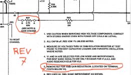
That’s an old diagram. Pls see attached picture for revision 7.
Thanks
One just landed in my shop this week. Half of the 47V zeners were shorted. Replaced the entire string. The thing that doesn't set right with me is that the bottom most diode in the string measures only about 27V instead of 47V, for the first few minutes. Eventually it starts to balance out. When it first starts up, the top of the string measures about 426V and then settles to 392V, which is close enough to the 396V called out on the diagram.
While the preamp now operates, the V8 tube (12AT7) overheats dramatically. The plate glows orange and pulsates, indicating some type of LF oscillation happening. Curiously, the unit arrived with an ECC83 in this socket instead of the 12AT7 called for on the diagram.
The overheating is likely caused by U2's output (supposed to be 16V) being actually 21.6V. Since this is a feedback circuit, it's a troublesome one to troubleshoot. I've already replaced U2, but that's not the cause.
Basic diode check of all the diodes found no other bad diodes. My plan is to start looking at the components around U1 next, but if anyone has any time-saving suggestions along the lines of "I've seen this exact problem and the problem was xxx component" I will thank you for that. Time is money!
V8 in the schematic I have shows a 12AX7. Pop one end of the 1000pF C34 out and see if it measures as a dead short. The SP-8 I fixed had similar problems to yours and this cap had failed and done a lot of damage. This may be starting to happen and pulling up the DC voltage at the non-inverting input of U2.
Thanks. My schematic shows 12AT7, but the unit came with a 12AX7, so it's useful to know that some versions use this.
I'll check C34... only finding 2200 and 750 polystyrene caps on this board and no 1000pF cap connected to pin 3. None of the poly caps show continuity with pin 3 U2.
I have 6.9V on both pin 2 and 3 of U2, but 21.6V on the output which should be 16V.
The preamp runs after a couple minutes of stabilizing, but the overheating of V8 still means there's a problem.
This unit has quite the modifications done to it. No doubt these are related to the problem of U2 output being 20.6V instead of 16V. Two terminals of the LM329 are used, the third is cut off. The 1000 ohm resistor is going to pin 3 of U2. Then the IC to and to ground through IC. The 12.1 K goes to a point that sits 13 ohms off of ground. This is NOT what's on my schematic.
Anyone know what this modification is?


Anyone know what this modification is?
I would consider the option of designing out the opamps and support transistors from the power supply to the largest extent possible to simplify the obnoxiousness of the circuit. You'll definitely lose the muting relay in the process of doing this, but this would likely be the most time efficient way of getting this up and running.
Also triple check that the BH7 and AX7/AT7 aren't swapped.
If someone brought me one of these with a blown up power supply, I would likely go the route of obsessive simplification rather than trying to get everything working to spec again.
Also triple check that the BH7 and AX7/AT7 aren't swapped.
If someone brought me one of these with a blown up power supply, I would likely go the route of obsessive simplification rather than trying to get everything working to spec again.
The first thing I checked was whether all the tubes were in the correct sockets. They are.
I do feel a desire to "simplify" this monstrocity a bit, but my overarching philosophy is to get it working properly to spec. My latest measurements today indicate that the voltage on pin 3 of U2 is slightly low at 6.5V. Schematic shows 6.9 on both 2 and 3 pins. So now I'm pulling and measuring R51/52. I tried trimming R52 with a 1 meg resistor just to see how it affected the output and it pushed it up toward 23V from the 20.6V it was at. So I'm gong to measure R68 next. Maybe if I trim R68 until the output of U2 is at 16V required, that may be good enough, I don't want to run up the hours if I can avoid it.
I do feel a desire to "simplify" this monstrocity a bit, but my overarching philosophy is to get it working properly to spec. My latest measurements today indicate that the voltage on pin 3 of U2 is slightly low at 6.5V. Schematic shows 6.9 on both 2 and 3 pins. So now I'm pulling and measuring R51/52. I tried trimming R52 with a 1 meg resistor just to see how it affected the output and it pushed it up toward 23V from the 20.6V it was at. So I'm gong to measure R68 next. Maybe if I trim R68 until the output of U2 is at 16V required, that may be good enough, I don't want to run up the hours if I can avoid it.
Yeah, it's an unpleasant creation to work on. The repair bill for the one I worked on was about the highest I've ever charged anyone for fixing anything.

The B+ is way too high for this setup, the pass and error tube have too much to deal with, the zener string is overstressed as well, the whole power supply needs to be completely redesigned!One just landed in my shop this week. Half of the 47V zeners were shorted. Replaced the entire string. The thing that doesn't set right with me is that the bottom most diode in the string measures only about 27V instead of 47V, for the first few minutes. Eventually it starts to balance out. When it first starts up, the top of the string measures about 426V and then settles to 392V, which is close enough to the 396V called out on the diagram.
While the preamp now operates, the V8 tube (12AT7) overheats dramatically. The plate glows orange and pulsates, indicating some type of LF oscillation happening. Curiously, the unit arrived with an ECC83 in this socket instead of the 12AT7 called for on the diagram.
The overheating is likely caused by U2's output (supposed to be 16V) being actually 21.6V. Since this is a feedback circuit, it's a troublesome one to troubleshoot. I've already replaced U2, but that's not the cause.
Basic diode check of all the diodes found no other bad diodes. My plan is to start looking at the components around U1 next, but if anyone has any time-saving suggestions along the lines of "I've seen this exact problem and the problem was xxx component" I will thank you for that. Time is money!
I used to rebuild Dynaco FM-3's when PCB's were in their infancy. So I just redesign the PCB's with through hole plating minus the silksreen and solder mask. That's what I would do with the '8'!
Rip the regulator out,use a clc filter with poly caps caps and a juicey chole like a hasimoto lc 15-200.will sound awsome and be totally reliable.
- Home
- Amplifiers
- Power Supplies
- ARC SP8 tube reg rebuild